Gigabyte Z97X-UD3H-BK Motherboard Review
Gigabyte Z97X-UD3H-BK Layout
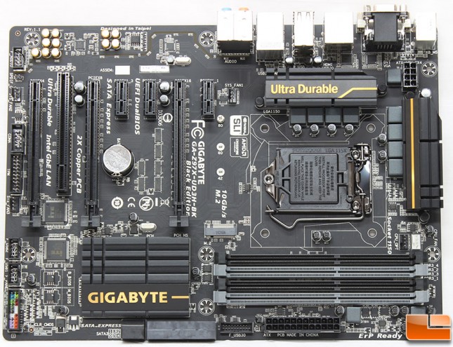
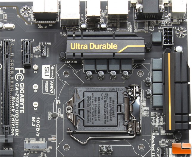
Taking a look at the overall layout of the Z97X-UD3H-BK, it follows a common layout for ATX motherboards; nothing immediately jumps out as being different. The 2x Copper PCB has a black color scheme with small yellow accent lines on the black heatsinks along with yellow lettering. There is additional yellow features that we can’t see at this point, and is a feature of Gigabytes separate PCB layers.
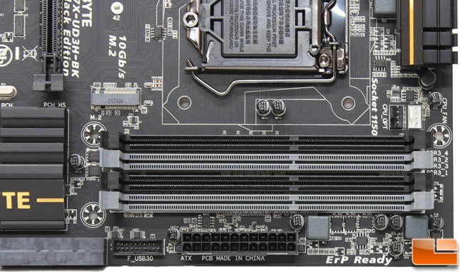
The Gigabyte Z97X-UD3H-BK is capable of supporting up to 32GB of DDR3 memory with dual channel architecture. For DDR3 memory speed, it has you covered all the way up to 3100 with overclocking. If you want to use the Intel XMP profiles, that is supported as well. In the lower left corner of the motherboard, there are two CPU fan headers above the DDR3 slots. Just below the DDR3 slots is the SuperSpeed USB 3.0 front header, and the standard 24-pin power connector.
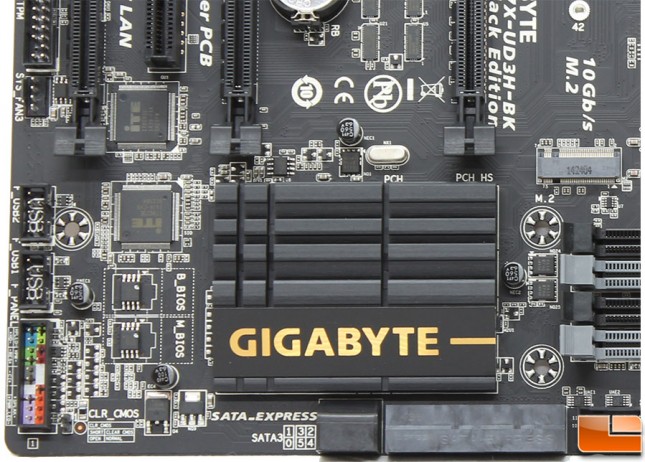
Moving along the bottom quarter of the Gigabyte Z97X-UD3H-BK, the large heatsink over the chipset stands out. Just below the black heatsink are the six SATA 6Gb/s and one SATA Express data connections, which we will discuss in a moment. Taking a closer look at the left edge of the board we find the front panel header, CLR_CMOS jumper next to the front panel header, two USB 2.0 headers and the Sys_Fan3 header with the TPM (Trusted Platform Module).
The Gigabyte Z97X-UD3H-BK has a total of six SATA 6Gb/s connectors and one SATA Express. If you are planning on utilizing M.2 or SATA Express device, you lose two of the SATA 6Gb/s connectors; the two bottom grey ones (SATA 4 and SATA 5).
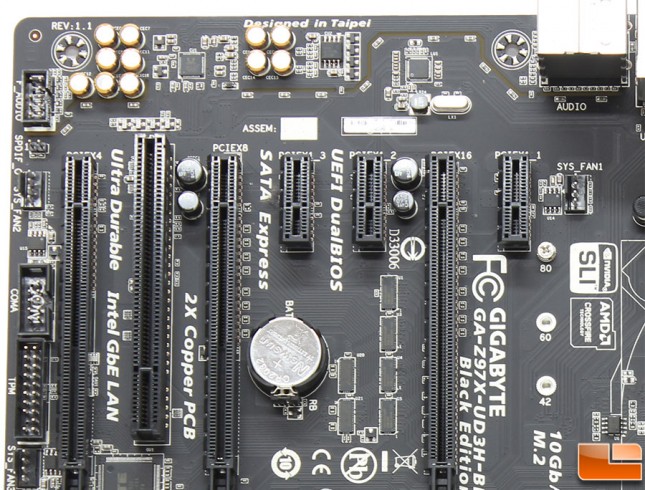
Continuing up the edge, we can barely see the Sys_Fan3 header, next is the TPM and COM headers. The Sys_Fan2 header is found here, along with the SPDIF jumper, and the front panel audio header. Next to the first PCIe x1 slot is the Sys_Fan1 header. The Gigabyte Z97X-UD3H-BK has a total of three PCIe x16 slots, three PCIe x1 and one old school PCI slot. Of the three PCIe x16 slots the first one (on the right) runs at x16, with the next running at x8, and the last one running at x4. Be sure to plug in your video card into the first one for the fastest conection. If you are more than one PCIe card this is how the PCIe lanes are shared:
1 x PCI Express x16 slot, running at x16 (PCIEX16): For optimum performance, if only one PCI Express graphics card is to be installed, be sure to install it in the PCIEX16 slot.
1 x PCI Express x16 slot, running at x8 (PCIEX8): (The PCIEX16 and PCIEX8 slots conform to PCI Express 3.0 standard.) The PCIEX8 slot shares bandwidth with the PCIEX16 slot. When the PCIEX8 slot is populated, the PCIEX16 slot will operate at up to x8 mode.
1 x PCI Express x16 slot, running at x4 (PCIEX4): The PCIEX4 slot shares bandwidth with all PCI Express x1 slots. All PCI Express x1 slots will become unavailable when a PCIe x4 expansion card is installed. When installing a x4 or above card in the PCIEX4 slot, make sure to set PCIE Slot Configuration (PCH) in BIOS Setup to x4.
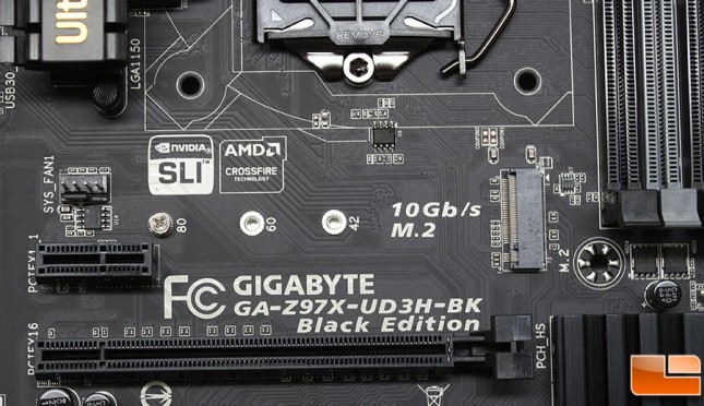
Below the Sys_Fan1 header and the first PCIe x1 slot, is the M.2 socket. Tucked away between the capacitors along the top edge is the Realtek ALC1150 high-definition audio codec that will provide up to 7.1 channel audio.
Speaking of the M.2 slot, the slot is located between the CPU socket and the PCIE x1 slot. There are three different types of M.2 form factors, the Z97X-UD3H-BK utilizes the M-Key, and supports M.2 SSDs that are 42mm, 60mm and 80mm in length (2242/2260/2280). For data transfer you can utilize SATA and PCIe M.2 SSD’s, so you’ll be able to get up to 10Gb/s (just as the motherboard says if you use a PCIe M.2) as the M.2 slot utilizes two PCIe Gen 2.0 lanes off of the Intel Z97 PCH.
It should be noted that the M.2, SATA Express, and SATA3 4/5 connectors can only be used one at a time. The SATA3 4/5 connectors will become unavailable when an M.2 SSD is installed on this board since they all use the same lanes.
In the upper right section of the motherboard, there isn’t much to check out; most of it we have already discussed. Between the two heatsinks is an 8-pin Aux power connector. The 1150 socket has the typical cover on it to protect the delicate pins.
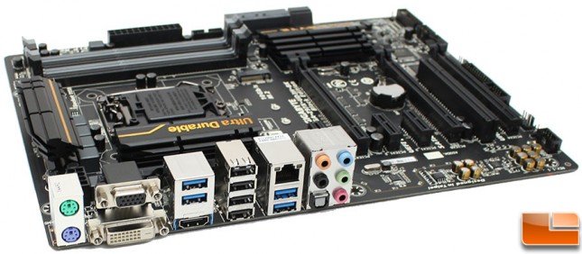
Gigabyte made sure to include plenty of I/O ports on the Z97X-UD3H-BK. First there is the old style PS/2 keyboard/mouse connections, VGA and DVI-D, two SuperSpeed USB 3.0 and HDMI make up the first three stacks of I/O connections. The next three include four USB 2.0, NIC and two SuperSpeed USB 3.0, with the last stack having five 3.5mm audio jacks and the optical SPDIF out.

