Gigabyte Z170X-UD5 ATX Motherboard Review
GA-Z170X-UD5 Layout
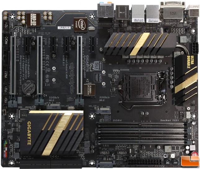
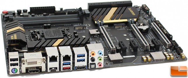
Taking a look at the overall layout of the Z170X-UD5, it follows a common layout for ATX motherboards; a few items immediately jumps out. Three of the chips have a cover on them have a highly polished gold colored finish (Turbo B-Clock, Intel GbE LAN, and Realtek ALC1150) and the three x16 PCI-E slots have a metal cover on them. The 2x Copper PCB has a black color scheme with gold colored accents on the black heatsinks along with gold lettering. There is additional yellow features that we cant see at this point, and is designed to separate the audio components from the rest of the motherboard; this has some additional functions, which we we will take a look at later..
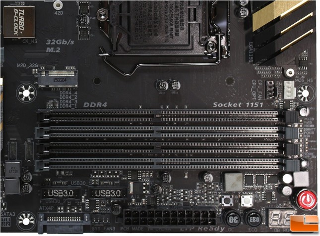
In the bottom corner we find some pretty standard items, the four DDR4 slots, which are capable of up to 64GB of memory in both ECC and non-ECC memory. Above the DDR4 slots are two CPU fan headers, CPU_FAN and CPU_OPT. To the right of the DDR4 modules is the voltage measurement points. While below the DDR4 slots are the dual USB 3.0 front headers SYS_FAN3, 24-pin motherboard power connector, a BIOS clear button (black button), Reset button (white button), Power (big red button), OC (load Gigabytes OC configuration), ECO (power-saving feature that reduces power consumption depending on workload), and Gigabytes debug LED.
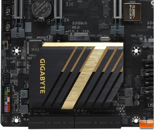
In the lower left section of the motherboard, there is a lot of things to discuss. Starting down the edge, there are two USB 2.0 headers, the BIOS switch, which has the two BIOS modules right next to it. Another fan header (SYS_FAN2), and the front panel connectors are all here. One of the accessories Gigabyte has included is their C-Connector, which makes these connections quickly and easily; especially once you have installed the motherboard and quarters get a little tight in that area. Along the bottom edge is various SATA connectors. The Intel Z170 chipset is covered by a large black and gold heatsink to help keep it cool.
Taking a glance at the horizontal ports on the edge of the motherboard, we find the SATA and SATA Express connectors broken into two groups. The first group contains two SATA Express and four SATA 6Gb/s connectors, while the second group contains one SATA Express and four SATA 6Gbp/s connectors. The first set of connectors and the bottom half of the second group is controlled by the Intel Z170 chipset, which is capable of RAID 0, 1, 5 and 10. If you happen to use the M.2 slots, be sure to read up which of the SATA slots are available depending on the M.2 configuration. The top two SATA 6Gbp/s in the second group of connectors is controlled by the ASMedia ASM1061 chip, these are not affected by using M.2 SSD’s.
Between the SATA ports and the 24-pin ATX power connects is a SATA power connector, the ATX4P PCIe power connector, that provides additional power to the on board PCI Express x16 slots when two or more graphics card to installed.
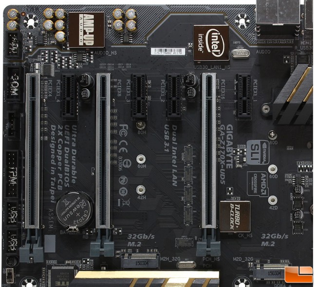
Continuing up the left side of the motherboard, is the Trusted Platform Module (TPM) header, the Thunderbolt add-in card connector, Serial port header, and the front audio header. Here we can see the PCI-Express slots, the three x16 slots with the metal shielding, the one on the right runs at x16, then x8 and the one on the left is the x4 slot; of course there are the four x1 slots as well. With the x16 PCI-E slots, you can run up to a 2-way SLI or 3-way CrossFire GPU configuration. One thing to be aware of, the M.2 slot that is between two x16 PCI-E slots, shares the bandwidth with the PCIEX4 slot (left most x16 PCI-E slot). If you use this M.2 slot, the PCIEX4 slot will become unavailable. If you are planning on using M.2 and SATA drives, you will want to evaluate which of the two M.2 ports to use since depending on the configuration, some of the SATA ports will not work. To the right of the main PCI-E x16 slot is the Gigabyte Turbo B-Clock chip, which allows changing the BCLK Frequency from 90MHz to 200MHz.
At the top edge of this area is the audio section, here we find the Realtek ALC1150 high definition audio codec with up to 115dB SNR. Gigabyte has also separated the audio from the motherboard to reduce interference from the other components. To show this, Gigabyte has LED lighting, which can be programmed to beat with the sound, pulse, solid or be turned off. On the Z170X-UD5, the LED is a gold color that matches the overall color scheme of the motherboard.
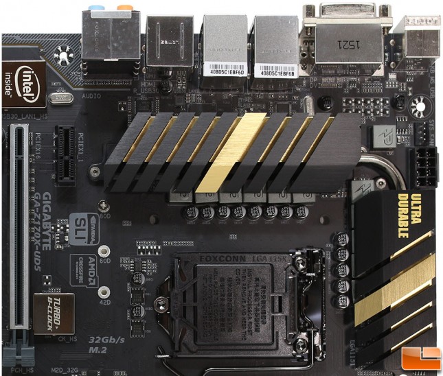
Nothing too fancy in the upper right quadrant, the Socket 1151 has the typical cover protecting the pins. Large heatsinks cover the MOSFETs around the CPU, and eight pin auxillary power connector in found along the edge. Next to the power connector is the final fan header, listed as SYS_FAN.
Gigabyte used a C style heatsink on the Z170X-UD5. This provides a bit more surface area for cooling the MOSFETs for the VRM and Intel 170 chipset “Southbridge”.
The back I/O panel features six clusters of various inputs. From the left, we have 2x USB 2.0, and a PS/2 Keyboard/Mouse port. Then a DVI-D and DisplayPort. The third cluster is where we start finding something new, one of the Intel Gigabit LAN, and the Type-C USB 3.1 port. Next is another Intel Gigabit LAN, a USB 3.0 and USB 3.1 ports. Then 2x USB 3.0 and HDMI connectors. The final cluster is the normal 7.1 audio outputs with TOSLINK.

