GIGABYTE P67A-UD7-B3 Motherboard Review
GIGABYTE P67A-UD7-B3 Motherboard Review

Earlier in the year we took a look at the middle of the road Intel P67 offering from GIGABYTE, the P67A-UD4. The P67A-UD4 proved to be a great board and we were extremely happy with it. Today though, we have the flagship P67 motherboard from GIGABYTE! The GIGABYTE P67A-UD7-B3 is the flagship motherboard for GIGABYTE’s Intel P67 series of motherboards. Being a flagship product, it does come with a flagship price. The GIGABYTE P67A-UD-B3 can be found for $314.99 plus $9.48 shipping. Considering the list of features that accompany the GIGABYTE P67A-UD7-B3 that price doesn’t seem to far fetched.
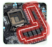
One aspect of the GIGABYTE P67A-UD7-B3 that helps separate the men from the boys, is the number of power phases for the CPU. The GIGABYTE P67A-UD4 uses a 12 phase power design. The GIGABYTE P67A-UD7-B3 that we have in front of us today uses a 24 phase design.

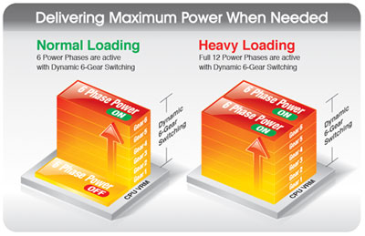
The 24 Phases of power being delivered to the CPU help to build a much more reliable power delivery system. The entire GIGABYTE 6 series of motherboards uses DUAL CPU Power Technology. This technology allows the CPU VRM power phases to split into a pair of power engines that work together. In the case of the P67A-UD7-B3 12 phases will be active while the other 12 are supplying power.

If you are using your shiny new GIGABYTE P67A-UD7-B3 for some light work like web browsing or any other task that isn’t very CPU intensive, the Dual CPU Power Technology will drop the number of phases that are active. Fire up an application like Folding at Home that will really use the CPU power that you have and the GIGABYTE P67A-UD7-B3 will increase the number of active phases up to the maximum 24 for the ultimate power delivery system.

Speaking of power phases, all of the GIGABYTE 6 series motherboards use an Intersil PWM controller. The Intersil PWM controller has been approved by Intel and is VRD 12 compliant. The Intel approved PWM controller offers SerialVID (SVID); this transfers power management information from the processor to the voltage regulator controller. This allows a more efficient signaling control between the CPU and PWM controller. What does this mean for the end user? Ideally, a more energy efficient system.

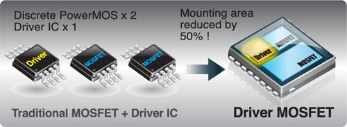
Traditional power delivery consists of a pair pf discrete PowerMOS and a driver IC. GIGABYTE has incorporated these components into a single chip. Doing this gives us several advantages. One of these advantages is size. The area required to mount the Driver MOSFET’s is reduced by 50%. This will leave real estate available on the PCB for other integrated devices. Driver MOSFET’s can achieve increased efficiency and higher power transfer at higher switching frequencies. This will help satisfy the growing power needs of the current processors.
One aspect of the Intel P67 chipset that is an issue for some is the limited number of PCI express lanes. Being limited to a total of 16 lanes some companies have thrown in a third party chip to add some lanes. ASUS used the PLX PEX8608 chip to add a few extra lanes on the ASUS P8P67 Deluxe to bring the total number of PCIe lanes to 24. 20 of which are usable by the PCIe graphics. GIGABYTE went a different route, they added the NVIDIA NF200 chip to give a total of 32 PCIe lanes to the P67A-UD7-B3. This allows the P67A-UD7-B3 to operate a pair of cards at x16 each or four cards at x8 each.
GIGABYTE P67A-UD7-B3 Specifications
| CPU |
|
| Chipset |
|
| Memory |
|
| Audio |
|
| LAN |
|
| Expansion Slots |
|
| Multi-Graphics Technology |
|
| Storage Interface | Chipset:
2 x Marvell 88SE9128 chips:
|
| USB | Chipset:
2 x Renesas D720200 chips and 2 x VLI VL810 hubs:
|
| IEEE 1394 | T.I. TSB43AB23 chip:
|
| Internal I/O Connectors |
|
| Back Panel Connectors |
|
| I/O Controller | iTE IT8728 chip |
| H/W Monitoring |
|
| BIOS |
|
| Unique Features |
|
| Bundle Software | Norton Internet Security (OEM version) |
| Form Factor | ATX Form Factor; 30.5cm x 24.4cm |
We have taken a look at some of the core features of the GIGABYTE P67A-UD7-B3 motherboard, though we have more to cover as we move along. Join us on the next page as we take a look at the packaging for the GIGABYTE P67A-UD7-B3!

Comments are closed.