Gigabyte P55-UD6 and P55M-UD4 Motherboard Reviews
Gigabyte P55-UD6 Images

The box is a bit flashy but I appreciate the fact that there are not any mythical creatures present. The box is helpfully plastered with icons pointing out all the features crammed into this box. When you see this box on a shelf you’ll know half a mile away that this board has 24 virtual power phases.

The bundle has enough documentation for two motherboards in addition to all the various SATA, PATA, and eSATA cables you’ll ever need.

Above you can see the Gigabyte GA-P55-UD6 motherboard in its entirety. Even with only a single required chipset Gigabyte still managed to take up the entire PCB and cover it in components.

Compared to the GA-P55M-UD4, the GA-P55-UD6 is an example of excess. The second memory channel features four memory slots, the PWM features 24 virtual phases, and the heat-pipe assembly resembles something found on higher-end X58 motherboards. That all being said there is some meaning to this madness. In theory the more phases in a PWM the smoother the output current ripple. The GA-P55-UD6 should be able to easily power any LGA1156 processor Intel releases, it’s only weakness will be the actual controller driving everything.

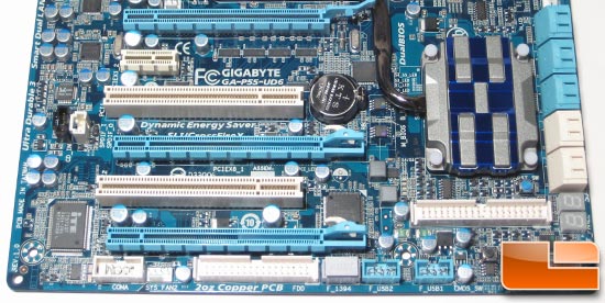
The bottom half of the GA-P55-UD6 is quite a busy spectacle. The expansion slots are setup to support SLI and Crossfire while leaving a PCI and PCIe slot available. Six SATA connectors are available through the PCH while four connectors are available through the add-on Gigabyte SATA2 chip underneath the heatsink. A useful debug LED is available in the bottom right corner next to the IDE connector.

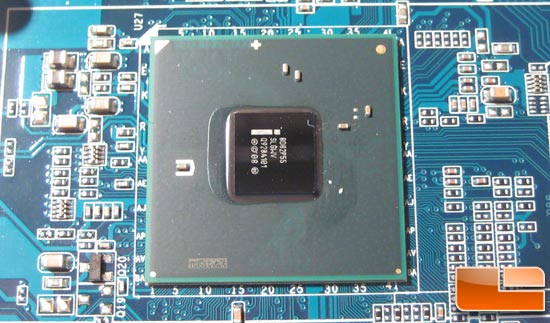
Stripping off the heatsink reveals the PCH chip between the socket and PCIe slots.

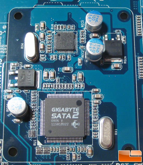
Sitting below the lower heatsink is the SATA2 chip providing connectivity to two white SATA connectors in addition to the IDE connector. Above it is one of the two JMB362 that provides connectivity to the other two white SATA connectors.

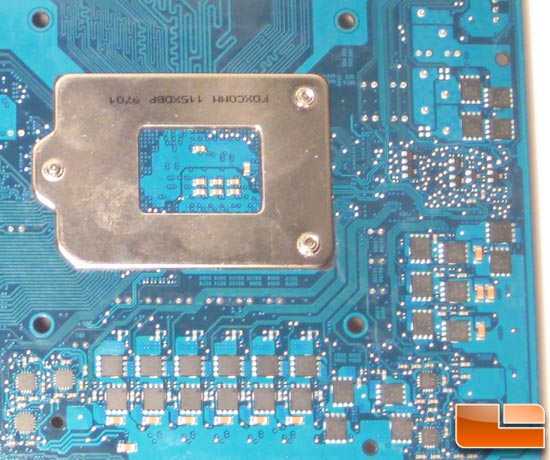
Removing the PWM heatsink unveils an Intersil ISL6336A 6-phase controller and half of the fets included in the 24-phase PWM. Where are the other half? Well..

They are on the back! Not much of a surprise as there physically wasn’t enough space on the front of the board. I’d have my concerns over heat dissipation but this will likely be a perfect case for heat dissipation via the 2 oz power and ground planes that run through the board. Considering how each “phase” will only need to convert ~5-10 watts and dissipate roughly 0.5-1 watt of waste heat I imagine everything will run smoothly.

Like most of Gigabyte’s high-end boards the GA-P55-UD6 is packing some connectivity. 6 sound jacks along with an optical and coaxial output are provided by the Realtek ALC889A codec. Something new to spice things up are the bottom two awkward yellow USB connectors. Those are actually combined eSATA connectors featuring power of eSATA AND USB 2.0 connectors. I like the flexibility Gigabyte included with those connectors, now if only eSATA and USB were to merge and have a baby called eUSB or USATA or something like that. The two ethernet ports are provided by two RTL8111D gigabit ethernet modules that support ethernet teaming if your network supports it. Last up you have two FireWire ports and a PS/2 port hanging in there like a blast from the past.

Comments are closed.