GIGABYTE GA-X79-UD7 Motherboard Review
GIGABYTE GA-X79-UD7 3D UEFI BIOS

When we first boot the GIGABYTE GA-X79-UD7 into the new 3D BIOS we are presented with a shot of the board and a list of pages below. At first though you may think that the you navigate through the 3D BIOS with the pages listed on the bottom of the page. Well, you can do that too. You can also highlight the area of the GIGABYTE GA-X79-UD7 that you want to work on, and select it with your mouse. That will bring up a overlay page with options for that feature.
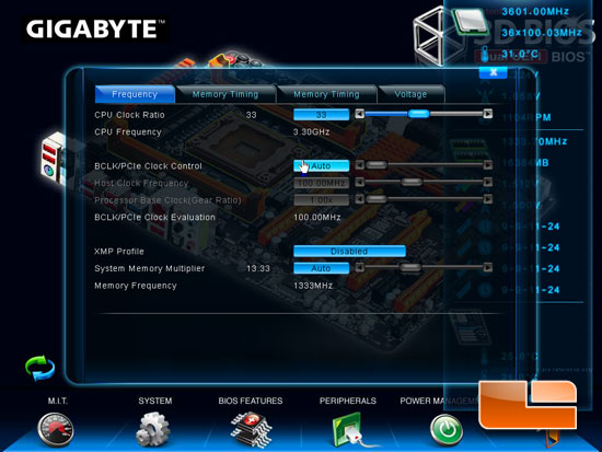
The first area of the GIGABYTE GA-X79-UD7 that we selected is the CPU socket. Once the overlay is displayed we can adjust CPU settings and overclock it right form here. We can adjust the CPU clock ratio, Bclk/PCIe Clock frequency, and memory frequency.
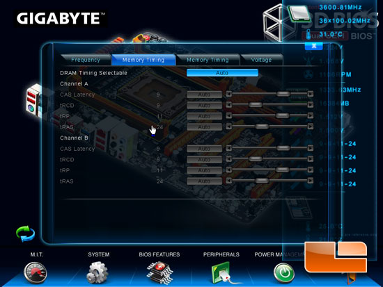
We can also set the memory timings for all four DIMM channels on the GIGABYTE GA-X79-UD7.
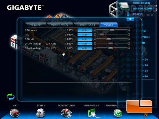
We also have the option to tweak the CPU Vcore, IMC, CPU Vtt, and the DRAM Voltage across all channels.

If we select the Rear I/O panel we can enable the onboard audio and LAN controller.

As well as control the options for the USB 2.0 and the SuperSpeed USB 3.0.

When we select the VRM area of the GIGABYTE GA-X79-UD7 we have the options for the GIGABYTE 3D Power. On the first tab we have the control for the PWM Phase Control, CPU PWM Switch Rate, CPU Vtt PWM Switch Rate, and the IMC PWM Switch Rate.

Switching over to the Voltage tab, we can set the Vcore LLC, Vcore Protection, Vcore Voltage Response, CPU Vtt Loadline Calibration, and the IMC Voltage Loadline Calibation.

Moving over the the Current tab, we can adjust the protection levels for the Vcore Curent Protection, CPU Vtt Current Protection, IMC Current Protection, and the DDR Current Protection for channels A/B/C/D.

The Final tab of the 3D Power options it the Thermal protection. Here we can set the thermal limits for the Vcore PWM, and DDR PWM’s for all four channels.

The GIGABYTE GA-X79-UD7 3D BIOS lets us set the bootup NumLock state, Full Screen Logo Show, Intel Virtualization Technology and Intel VT-d.

The GIGABYTE GA-X79-UD7 has three different fans that can be controlled by the smart fan technology. The CPU fan speed, first system fan and second system fan can all be managed by the PWM value or set to full on.
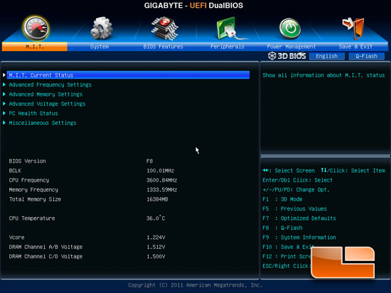
If you prefer to navigate through the BIOS the more traditional way the GIGABYTE GA-X79-UD7 allows that as well. Above we can see the M.I.T. page. Here we can gain access to the M.I.T. current status, Advanced Frequency Settings, Advanced Memory Settings, Advanced Voltage Settings, PC Health Status, and Miscellaneous settings. The Miscellaneous settings doesn’t have any settings in it with the F8 BIOS revision, likely saving the space for future revisions. Below the sub-page access is some basic information about the board settings. We can see the current Bclk, CPU frequency, memory frequency, total memory size, CPU temperature, and voltages for the Vcore and DRAM channels.
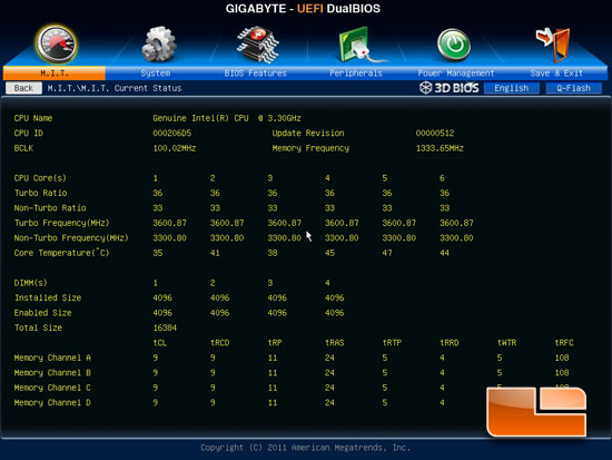
The M.I.T. Current status shows us a much more detailed view of the current system settings including a per core view of the CPU frequency, how much memory is installed in each DIMM slot, and the current memory timings.
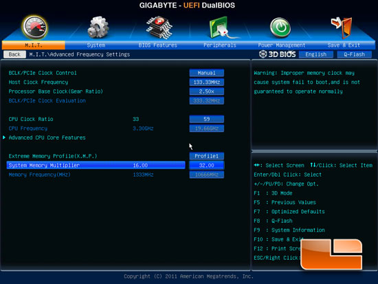
Sticking our heads into the Advanced Frequency Settings we can see all the maximum settings of the GIGABYTE GA-X79-UD7. The highest Host Clock Frequency is 133.33MHz, though that can be increased by the Processor Base Clock (Gear Ratio) which can be increase to 2.5x which brings the Bclk/PCIe Clock Evaluation to 333.32MHz. The maximum CPU multiplier is x59. We can also enable the Extreme Memory Profile(X.M.P.), or manually set the system memory multiplier up to a maximum of 32.
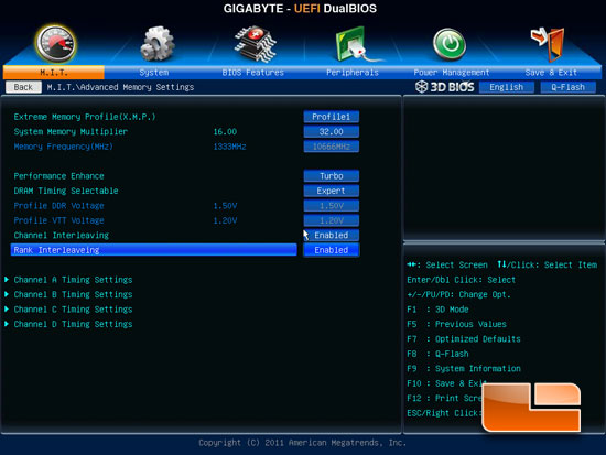
Under the Advanced Memory Settings page we can once again set the X.M.P. profile or set the system memory multiplier to your own preference. Moving down on the page we can find the Performance Enhance setting, DRAM Timing Selectable, Channel Interleaving, Rank Interleaving, and the Memory Timing sub-pages.
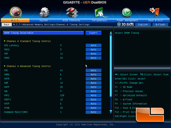
Taking a quick look at one of the Memory Timing settings pages, we can set all of our memory timings and sub-timings here.
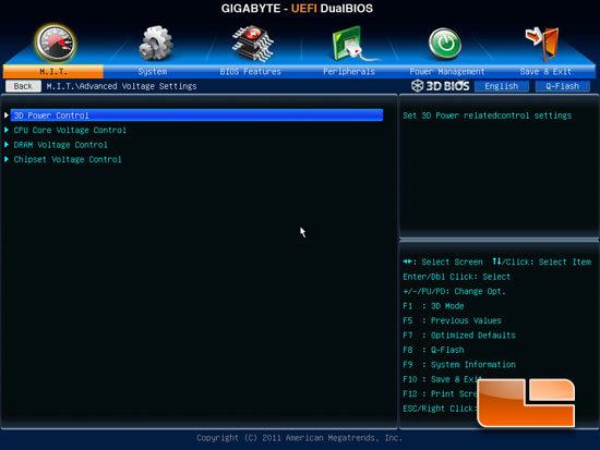
Entering the Advanced Voltage Settings page we can access the 3D Power Control, CPU Core Voltage Control, DRAM Voltage Control, and the Chipset Voltage Control.
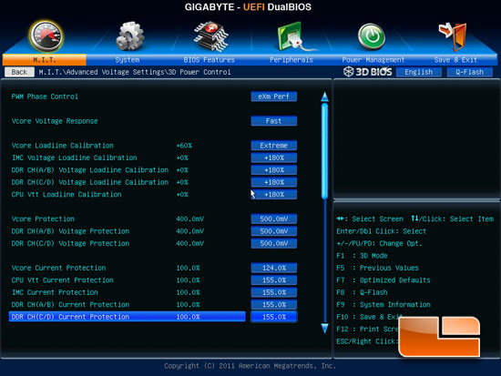
Within the 3D Power Control we can adjust the the various LoadLine Calibration settings and the voltage protection settings throughout the GIGABYTE GA-X79-UD7.
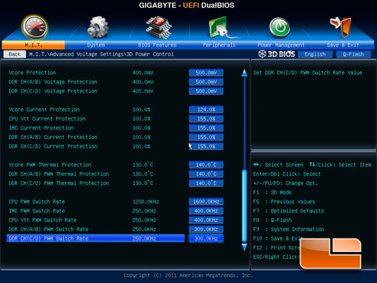
Scrolling down the 3D Power Control page we have a few more options for protections and the various PWM switch rates are hiding out at the bottom of the page.
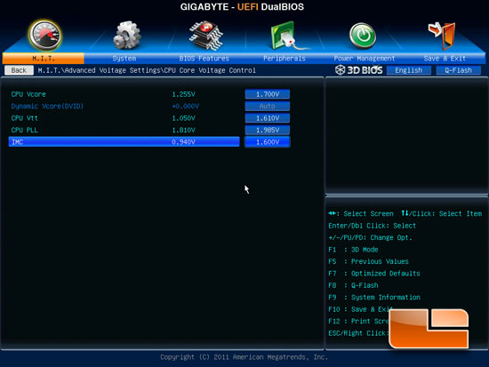
The CPU Core Voltage Control is pretty self descriptive, we can adjust the voltages for the CPU Vcore, CPU Vtt, CPU PLL, and the IMC voltage.
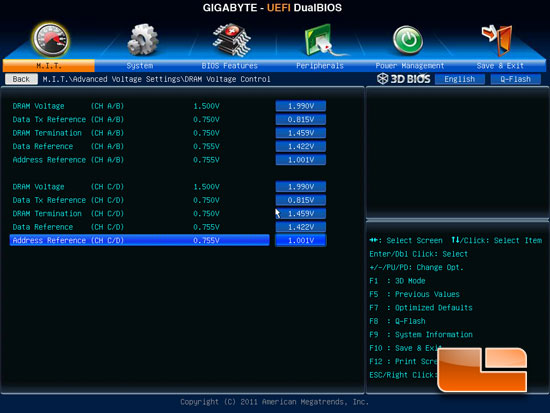
Once again the DRAM voltage page is self explaining. We can adjust the DRAM Voltage, Data Tx Reference, DRAM Termination, Data Reference, and Address Reference for Channel A/B as well as Channel C/D independently.
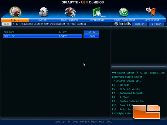
The Chipset Voltage page has the voltages for the PCH Core and the PCH 1.5V.
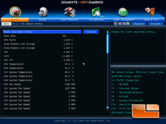
The PC Health Status displays the various temperatures, voltages and fan speeds of the GIGABYTE GA-X79-UD7.
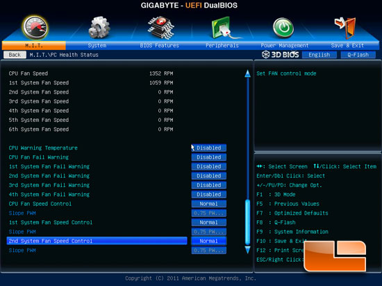
Scrolling down on the PC Health Status we can set the various temperature warnings, Fan Fail warnings, and the Smart Fan Control can be found here as well.
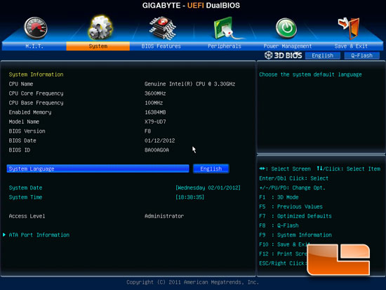
The System page of the GIGABYTE GA-X79-UD7 displays the same basic information we saw in the M.I.T. page, as well as having the ability to set the System date, time and language. At the bottom of the System page we have an additional page for the ATA Port information.
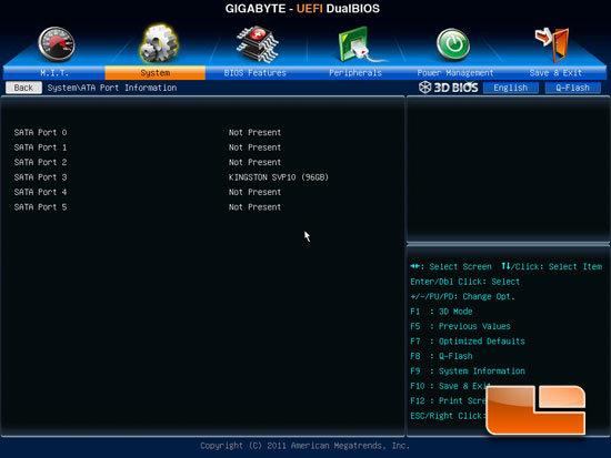
The ATA Port information shows us what drives we have plugged into which port. Above you can see that our Kingston SSDNow V100 SSD is plugged into SATA Port 3 which is one of the SATA II 3Gbps ports.
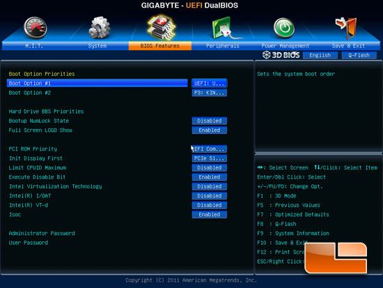
Moving over to the BIOS features page we can set our boot device order, and a couple of the CPU technologies. At the bottom of the page we have the security options that we can set the Administrator password and the user password.
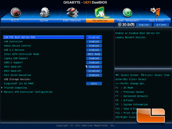
The peripherals page allows us to enable or disable the onboard devices and set the Intel SATA Controller mode. As we can see, the Intel SATA Controller mode defaults to AHCI. This is pretty common these days but we still see a few boards that default to IDE.
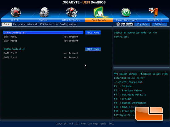
The Marvell ATA Controllers default to AHCI as well.
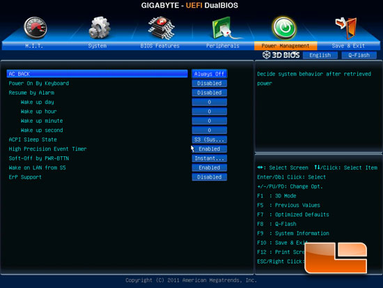
Above we can see the various power management features on the GIGABYTE GA-X79-UD7.
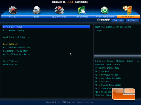
The final page of the GIGABYTE GA-X79-UD7 3D BIOS is the save and exit page. Here we can save and exit, exit without saving, or load the optimized defaults. We can set a boot override, and set up our saved profiles or load a previously saved profile.

Comments are closed.