Fractal Design Arc Midi R2 Mid Tower Case Review
Arc Midi R2 Internal Impressions
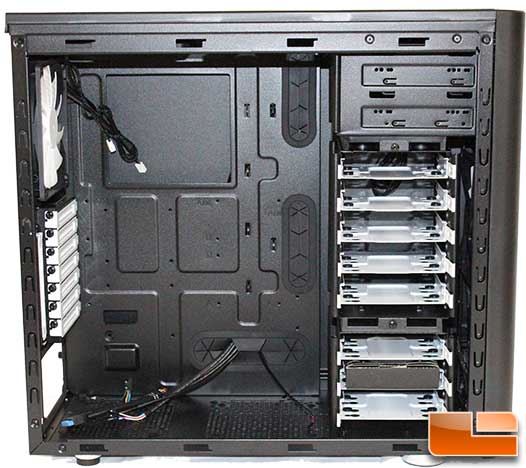
The interior of the case has the usual suspects. A large CPU cooler bracket cut-out, large enough to support all positions of the CPU. Five (three large and two small) cable management holes, each with a rubber guard to keep things tidy.
The Arc Midi R2 is compatible with ATX, Micro ATX, and Mini ATX motherboards, ATX PSUs up to 170 mm deep when using the bottom fan location (when not using this fan location longer PSUs – up to 270 mm deep – can be used), and CPU coolers up to 180mm in height. As far as graphics cards are concerned, the Midi R2 supports cards up to 290mm in length with the top HDD cage installed (with the top cage removed, there’s room for graphics cards up to 430mm in length).
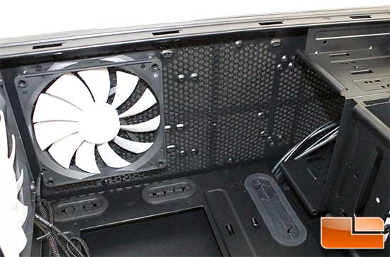
The top view provides another look at the top fan or water cooling radiator location. One of the 120mm/140mm fan locations looks like it might interfere with the top optical drive bay. However, it doesn’t.
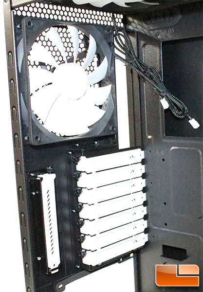
The back panel is pretty normal as well. The expansion port covers are white which contrasts with the black case nicely. Each of the covers are held in place by a thumbscrew. While the main expansion covers are solid, the extra is vented to help with airflow. The 140mm included exhaust fan can be replaced by a small 120mm water cooling radiator if desired.
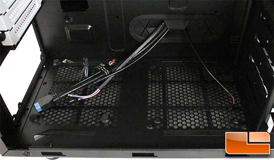
On the bottom portion of the case we find that Fractal Design has included several rubber feet to reduce the vibration from the power supply, in addition there is another place to install a 120mm or 140mm fan, or a 120mm water cooling radiator. However, if you reposition the hard drive cage to install a 240mm radiator in the front, this will not be an option.
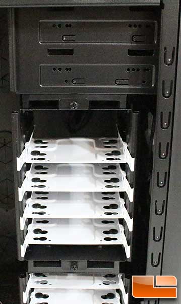
The 5.25” drive bays are only semi-tool-less, while they do not have any pre-installed tool-less clips, Fractal Design does include thumbscrews to make the installation fairly easy. The main 3.5” drive cage will hold five 3.5” devices on trays, these trays will support a 3.5” or 2.5” drive. This cage can be easily removed by two thumbscrews at the top and bottom.
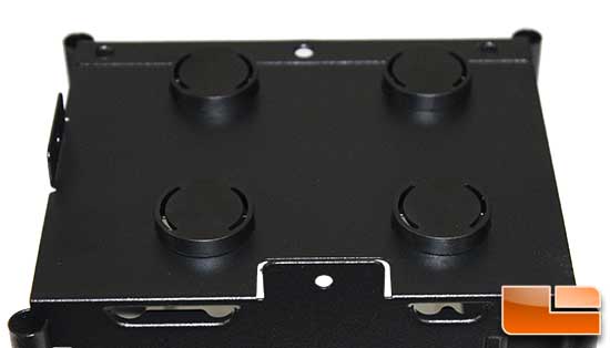
Once removed, the guides which ensure the hard drive cage is installed correctly can be seen. This is a very easy method of lining up the cage, anybody can do it.
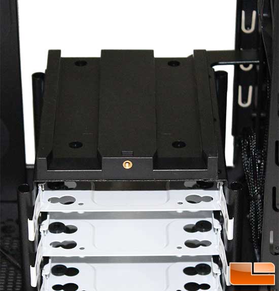
In order to line up with the guides, the hard drive cage also needs to have guides to slide into the previous guides lines. Large plastic guides make it easy to slide into the guide lines, while keep it feeling extremely solid.
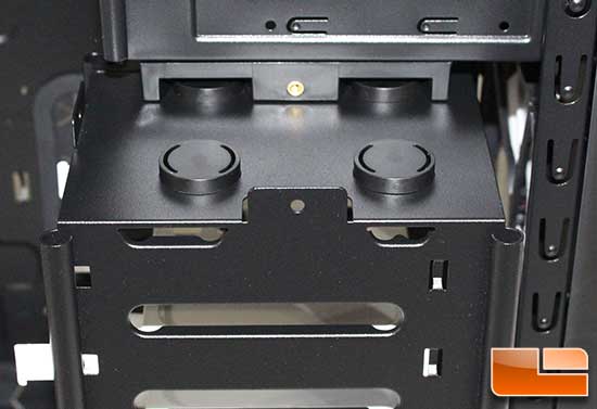
To reinsert the cage, simply line up the guides and slide it in. You can have it oriented in one of two directions depending on your preference.
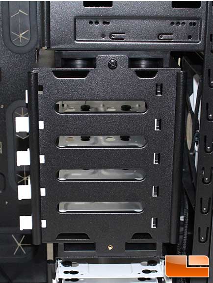
Here the cage has been rotated so the drive would face the motherboard.
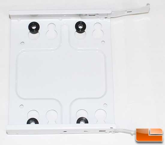
The drive trays are metal with rubber grommets to reduce the vibration from 3.5” hard drives. The drives are secured to the tray with the included screws. The tray then slides into place and is secured by clips on the edge of the grips.
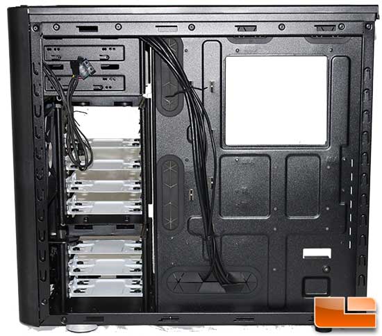
On the back of the motherboard tray there are six places to use the included cable ties to attach the cables, as well as room for two SSD’s. These need to be installed before the motherboard as the screws need to be installed from the other side. In addition, you must use straight SATA cables as there is not enough room to use the 90 degree connectors.
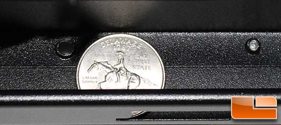
Behind the motherboard tray there is also a large amount of room to route your cables. Using a US Quarter as a reference, it is obvious how much space there is. For those that don’t know, the US Quarter Dollar is 0.955 inch in diameter (24.26 mm).

Comments are closed.