BIOSTAR Hi-Fi A85W Motherboard Review
Hi-Fi A85W Layout
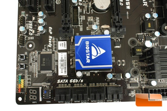
We are starting off around the area of the Southbridge then will make our way around the entire motherboard. I am going to start on the bottom right and I will go left then up. This motherboard as we can see can utilize up to eight SATA 6GB/s (SATA 3) based HDD/SSDs. We can also use RAID 1,0,10 on this particular motherboard. To the left of the SATA ports is the CMOS chip, to the far left hand corner is the LED Diagnostic indicator. Making our way up the left hand side edge of the motherboard we start off with the Front IO on/off header, located directly above the header is on board on/off and reset buttons. Moving up we can see that this motherboard supports up to four front USB 2.0 ports. Nestled directly above the CMOS and the Diagnostic indicator LED is the ITE chip that will monitor fan speeds and various temperatures of the motherboard.
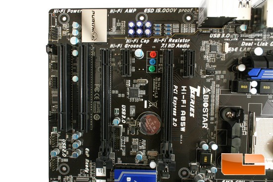
We are now making our way over the PCI-E/PCI expansion ports, or top left hand corner of the motherboard. On the far left hand edge of the motherboard right above the USB 2 headers is fan header #1 (I am counting these as I see them), followed by two COM headers, a SPDIF Audio header, and up by the corner is the front audio header.
Looking at the PCI-E/PCI expansion ports, starting from the right moving left, Biostar includes a PCI-E x1 port, followed by a full length PCI-E x16 port (these ports are only PCI-E Gen 2 and not the newer standard of PCI-E Gen 3). Biostar places the CMOS batters and the clear CMOS jumper in the space of no expansion ports, because our video cards typically will also occupy the adjacent port/space, so this should allow us enough room to be able to clear the CMOS while we have a video card(s) installed onto this motherboard. Still making our way left, we are given another PCI-E x1 port, then an additional full length PCI-E x16 expansion port. Now, keep in mind this expansion port is only rated at a x4 bandwidth, and not the full x16, or half x8 lanes. You can run AMD’s Crossfire on an x4 PCI-E but the performance will take a hit on the limited bandwidth of this expansion port. Looking down the second full length PCI-E expansion port is a header; this is the front USB 3 motherboard header (I will comment a bit more on this later). Then moving to the left side of the second full length PCI-E x4 expansion port are two standard PCI expansion ports.
Directly above the PCI-E/PCI expansion ports is where the Hi-Fi audio chip is located. The actual audio controller is underneath the shiny metal cover with Puro Hi-Fi imprinted on it. To the right of the Hi-Fi audio controller are some capacitors, and some resistors that will help clean up the audio signal while giving us a much clearer and crisper sound out of the onboard audio.
The placement of the front USB 3.0 header is in an awkward spot; the front USB cable from our chassis can be rather thick as well as not very flexible, which may cause some minor problems on our cable management.
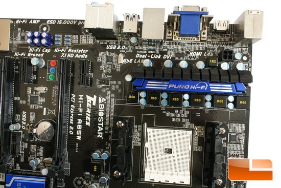
We are now making our way over to just in front of the rear IO ports of the Hi-Fi A85W motherboard. Biostar places the EPS CPU power in between the mosfets and the rear IO ports. I actually did not care for its placement because it did make plugging in the EPS power cable a bit difficult (I guess I got spoiled by previous motherboard that placed this power plug onto the far edge of the motherboard). Biostar is using a six phased power distribution for the APU itself. Considering the AMD Trinity 5800K APU only uses up to 100 Watts of power this should provide us with more than enough power to feed our APUs. Directly above the PCI-E x1 expansion port is fan header # 2.
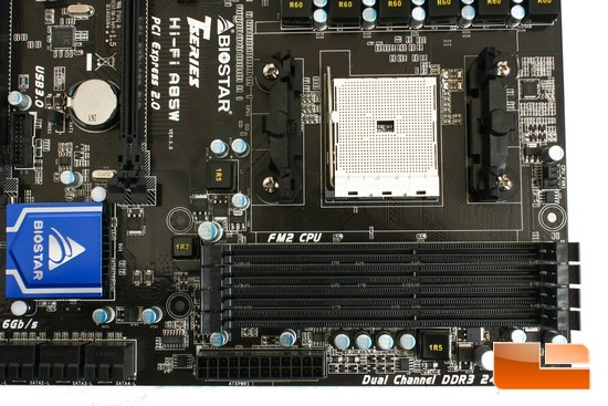
Here we are looking at the memory DIMMs of the Hi-Fi A85W motherboard. The AMD Trinity APU only has the capability of running our memory in dual channel, but this motherboard can utilize up to 64 Gigabytes of memory. Just below the memory DIMMs is the main 24 pin power plug. Now on the right hand side edge of the motherboard and directly above the memory DIMMs is fan header #3.
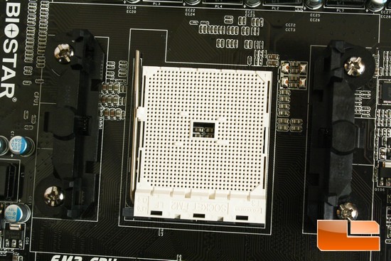
The APU socket area is fairly clean and is free of any large obstacles so that we can use a multitude of different CPU coolers on this motherboard. I should mention that we can use previous generation AMD CPU/APU coolers directly. We are not able to mount a Llano based APU onto this motherboard; the socket pin layout is different from what the AMD Llano APU uses.
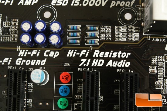
Here is a better picture of the Hi-Fi capacitors and resistors that Biostar included that will help make our sound from this motherboard clearer. BIOSTAR told Legit Reviews that the capacitors that they are using are also used on Onkyo and Yamaha receivers, so they are not using generic or cheap Chinese made stuff.
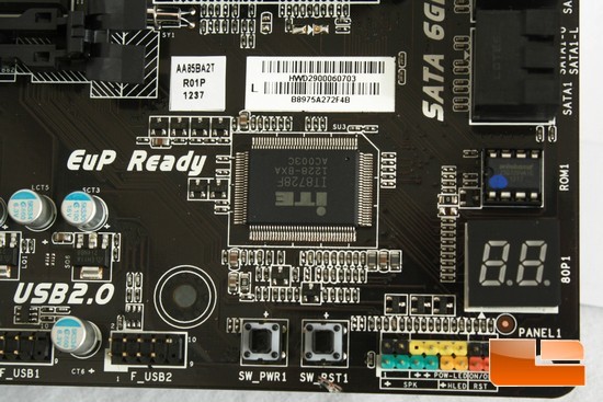
Here is a close up shot of the ITE chip that is being used to control the vitals of the Hi-Fi A85W motherboard.
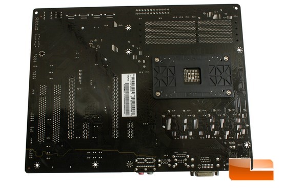
This is the backside of the motherboard; again, it looks pretty clean and nothing should give us any issues when installing this motherboard into our chassis.
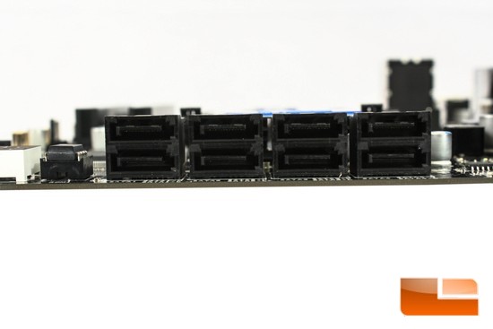
The eight SATA 6GB/s ports are all at a 180° orientation to the motherboard.
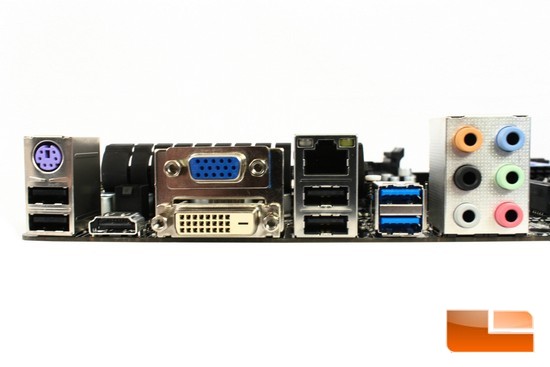
Here are the rear IO ports of the motherboard, starting left and working right. Biostar includes a PS2/2 USB 2.0 header and an HDMI VGA port, followed by a D-Sub/DVI VGA header. To the right of the D-Sub/DVI VGA header is the included Gigabit Ethernet/two USB 2.0 port header, then we get included two USB 3.0 rear motherboard headers. To the far right is the included 7.1 channel analog audio port header. This motherboard does not come with an Audio Optical port/header. This did not quite settle right with me, because I no longer use the analog connectors and only have the Toslink Audio optical cable to my home stereo amplifiers.
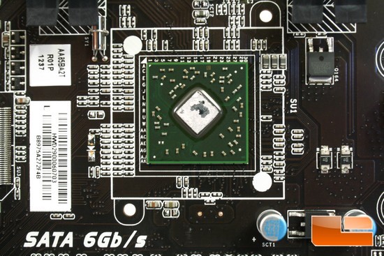
I went ahead and removed the Southbridge cooler to get a better look at this controller chip.
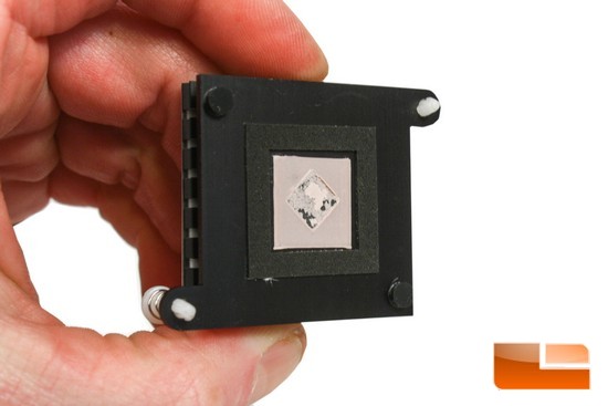
I also wanted to see what kind of thermal interfacing material was being used on this motherboard. Biostar uses the traditional pink thermal interfacing pad; I never really cared for this type of thermal interface material myself.
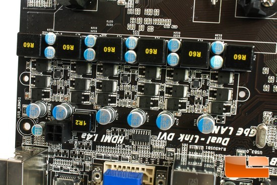
Removing the APU Phased power heat sink reveals that Biostar uses 18 traditional mosfets that will power the AMD APU.
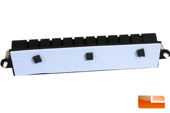
We are looking at the underside of the APU phased power heat sink. Again, much the traditional thermal pad material I have seen on multiple different motherboards.
I went ahead and installed the AMD 5800K Trinity APU into the motherboard. Just make sure that you lift the little silver lever on the side of the socket area prior to installing the APU. Also make sure you align the pins of the APU to the socket properly. DO NOT force the APU into the socket; if it does not go in smoothly, then the APU and socket is not aligned properly.

Comments are closed.