ASRock Z170 OC Formula Motherboard Review
Z170 OC Formula Layout
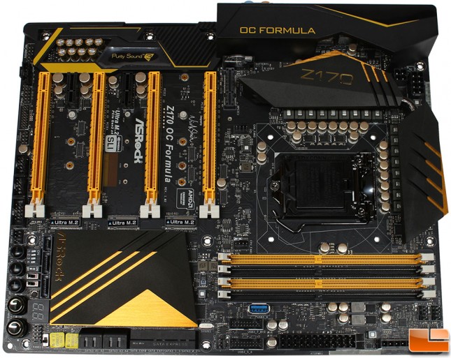
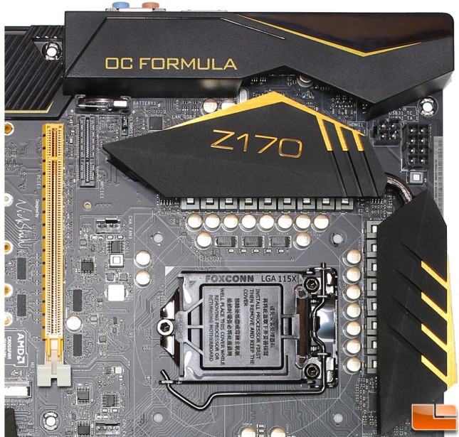
The overall layout of the ASRock Z170 OC Formula is a familiar one as not much changes from one motherboard to the next. A few unique features immediately jump out, which we will take a closer look at when we look more closely at the motherboard. The overall look of the motherboard features a matte black PCB and gold colored highlights, in addition it is a little different with a couple large oversize heat sinks on the Z170 chipset, and the MOSFETS around the CPU, and a rear I/O port cover that extends from edge to edge. There is also a USB Type-A connector is built onto the motherboard below the DDR4 slots.
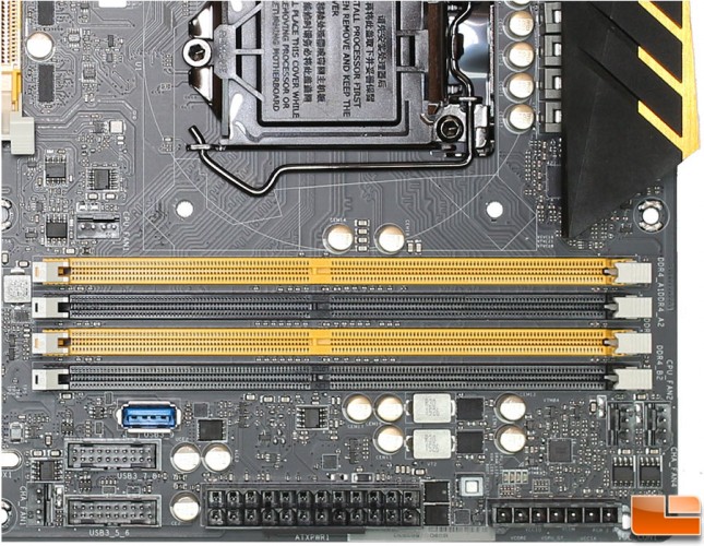
Starting in the bottom right corner, we find some very familiar features. Obviously we have the four DDR4 slots, which are capable of supporting up to 64GB of memory, in speeds all the way up to 4500MHz (and beyond); the BIOS only shows up to 4133MHz though. Dual SuperSpeed USB 3.0 internal headers and the previously mentioned USB 3.0 Type-A connector is right under the DDR4 slots. A standard 24-pin main power connector is provided in the usual spot. Next to that we have seven pins to check voltage. In this area are four PWM fan headers, CPU_Fan1 is above the DDR4 slots, CPU_Fan2 and CHA_Fan4 is to the lower right of the DDR4 slots, and finally CHA_Fan1 is to the left of the USB 3.0 headers. The Internal Type-A port will be useful to some if you happen to have an older case that has USB 3.0 but used a pass-through cable to the back of the motherboard, plugging in a flash drive for testing/drivers, or if you are really courageous plug in a fast flash drive to use as as boot device (ok that might be a stretch, but it is possible), this is also where you can put in a USB drive to log into Windows automatically.
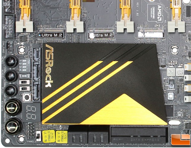
Moving along to the lower left quadrant of the motherboard we find a cluster of buttons, switches, DeBug LED, front panel connectors, SATA ports, dual BIOS chips and number of other features; this is a pretty busy corner of the motherboard. To the left of the Z170 heatsink is a SATA Express and two SATA 3 ports, these ports share bandwith with the M2_3 port, which is located right next to the ASRock logo on theZ170 heatsink. For old-style DIP switches are used to turn on/off the PCI-E x16 slots, another switch selector is if you are using LN2, “Slow Mode” switch and XMP profile enablment switch is next. The we have the first button, which is the Direct Key button, which allows you to boot directly into the BIOS without having to press the Delete key (restart from Windows into the BIOS). Dr Debug LED is found here with common error codes found in the user manual. Front panel connectors, and the BIOS selection switch. Along the left edge we find a Com port, and CHA_Fan2 connectors. Then we get into the five large buttons; the first button is Menu, which provides a quick method of entering the boot menu. Rapid OC buttons -/+ allow quick access to raising or lowering the CPU Ratio for overclocking. Finally we have a Rest and Power button, which is useful in some situations, however I still encountered several times in overclocking where I had to unplug the power supply to use the clear BIOS button.
Along the edge of the motherboard are two sets of horizontal SATA ports; all of which are capable of supporting up to 6Gb/s. The first set contains four SATA ports, while the second set contains two SATA Express and four SATA ports. These two SATA Express ports share bandwidth with the SATA ports next to them, and two of the M.2 slots (M2_1 and M2_2). For the first four SATA ports, ASRock has included the ASMedia ASM1061 chip to provide SATA ports that do not share bandwidth with the M2 or SATA Express ports.
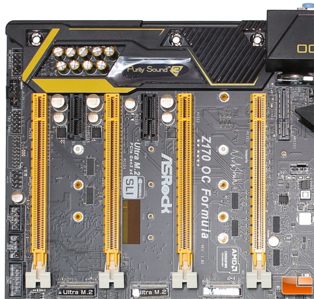
Moving up the edge of the motherboard, we have a pair of USB 2.0 headers, the Power LED and Speaker headers which are commonly found in the front panel cluster, Trusted Platform Module (TPM) Header, Thunderbolt 2 and 3 AIC Connectors and finally the front panel Audio headers. The four yellow PCI-E x16 slots are easily identified, depending on your configuration, the speed of them will change. For example a single GPU will run at x16 in PCIE1, while two cards in PCIE1 and PCIE4 will run at x8. The two 1x PCI-E slots, the first one (PCIE3) is based on PCIE 3.0 and is ASRock’s new Flexible PCIE port allowing you to install any PCIE card into this slot, however it’ll only run at PCIE3.0 1x speed. The other 1x PCI-E slot is a PCIE 2.0 port. To the right of the first PCI-E x16 slot is the new 1x Half-Size Mini-PCI Express slot. With the four PCI-E x16 slots, you are able to run up to Quad SLI or CrossFireX.
Nestled between the PCI-E x16 slots is the three Ultra M.2 ports, which as we previously mentioned share bandwith with the other SATA ports. Above the PCI-E slots is the audio section, which is covered by a large cover, extended from the rear I/O port cover. Under the cover is the Realtek ALC1150 audio chip, along with two TI NE5532 amps.
The final quadrant of the motherboard includes the Socket 1151, under the standard cover to protect the pins during shipment. Under the Mini PCI-E port is the final CHA_Fan3 header. Near the BIOS battery is also a hard jumper used to clear the BIOS. There are two Aux power connectors, a four pin, and eight pin. In essence, they do the same thing, just depending on which one you want to utilize. Most will use the eight-pin, which also includes the four pin connector. However, if your power supply happens to have only an eight pin connector that doesn’t split into two four-pins, this can be useful.
The back I/O cluster six clusters of ports, along with a single easy to access button. Starting on the left, there are two USB 2.0 and a Keyboard/Mouse PS/2 port, then a BIOS reset button. Video inputs include DisplayPort and HDMI. There are two USB 3.1 Type-A ports, along with a Type-C. A pair of SuperSpeed USB 3.0, next to the Gigabit LAN and another pair of USB 3.0 ports. Finally, the audio cluster which has the normal 7.1 audio outputs along with a TOSLINK.

