Intel NUC Kit NUC5i5RYK Review – Broadwell Comes to NUC!
Inside The Intel NUC NUC5i5RYK
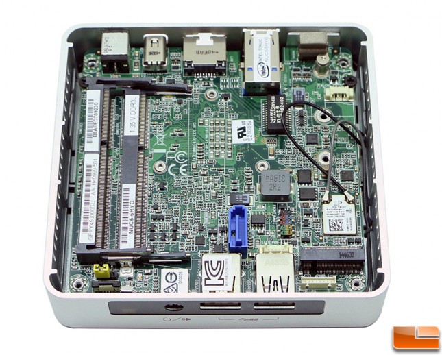
With the bottom cover removed from the Intel NUC NUC5i5RYK you can quickly see there are two DDR3L SO-DIMM slots and a M.2 slot for your PCIe SSD. The blue SATA III header in the middle of the board and front case panel connectors won’t be used unless you plan on putting this board in another chassis for a totally custom build. The yellow jumper is for the BIOS security pins that allow you to run the BIOS in normal, lockdown and reset modes. The little white and black thingy majiggy below the yellow jumper is the Near Field Communications (NFC) Vertical Flexible Printed Circuit Connector (0.5mm pitch).
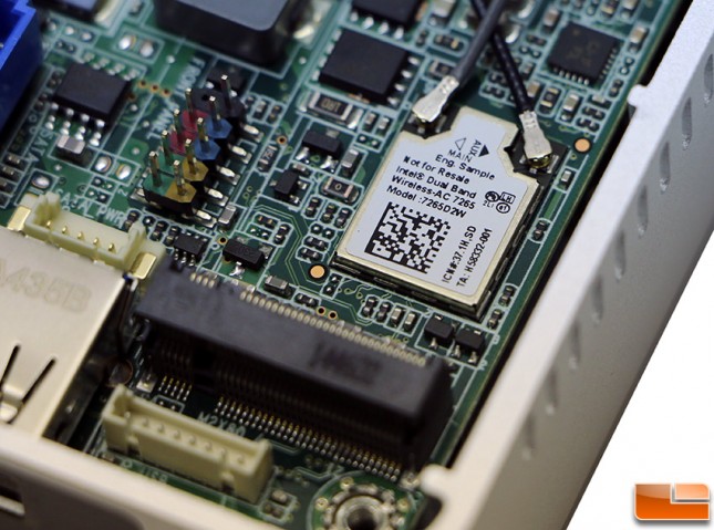
The Intel Wireless-AC 7265 wireless card is soldered down to the board with the wireless antennas already attached and routed. This 802.11ac Wi-Fi card is actually located under the M.2 PCIe slot, so it just goes to show how thin this solution is. In this picture you can also see two white headers. The white header on the left is a SATA power connector (1.25mm pitch) and the one below the black M.2 slot is the front panel dual-port USB 2.0 header (1.25mm pitch).
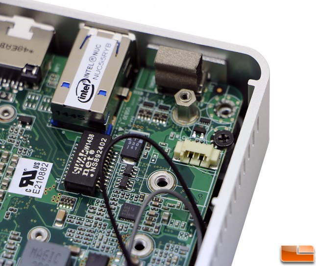
Above the wireless card you’ll see the standoff for the M.2 PCIe SSD. Intel has these three holes to support 42, 60 or 80mm long M.2 SSD cards. You can also make out the SWAP NS892402 Ethernet Transformer Module and a 4-pin auxiliary power connector.
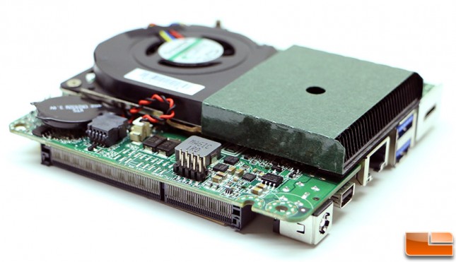
This angle shows just a sliver of the Copper heatsink base plate that Intel is using on the processor as well as the USB 2.0 header along the edge of the board that adds a pair of USB 2.0 ports if needed.
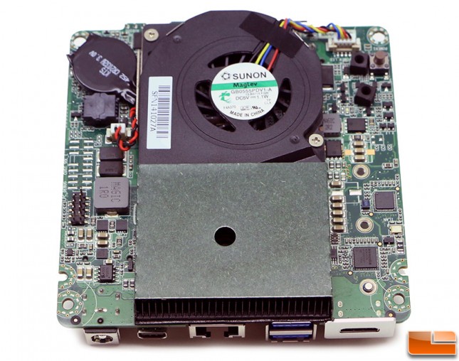
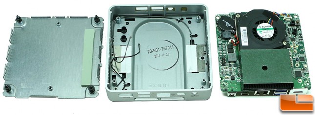
Here is a shot of the board outside of the case. Note the case has a thermal pad installed on the bottom plate to improve the thermal performance of M.2 devices since they operate at fairly high temperatures.
Let’s install the memory and storage drive into the NUC5i5RYK.

