GIGABYTE G1.Killer Sniper 5 Intel Z87 Motherboard Review
GIGABYTE G1.Sniper 5 Layout
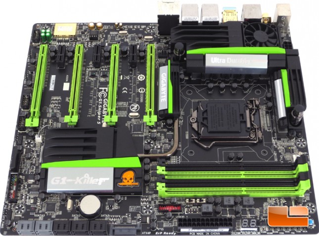
I’m not normally one for bright and shiny colors like we see on the GIGABYTE G1.Sniper, but I’ll admit that it’s grown on me. Overall I like the look of the G1.Sniper 5 and even the bright green looks good.
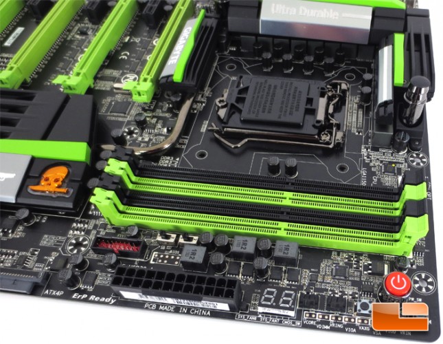
Starting out in the area below the Intel LGA1150 socket, there are a number of noteworthy features here. First off, the GIGABYTE G1.Sniper 5 supports dual channel memory at speeds up to 3000MHz (O.C.) and down to 1333MHz. If you wanted to max out the memory capabilities of the Sniper 5 mobo, you would need to fill each of the four DIMM slots with 8GB modules for a total of 32GB. Just below the DIMM slots is a pair of dip switches, SB, and BIOS_SW. The SB dip switch will enable or disable the single or dual BIOS modes while the BIOS_SW will bounce you between the main BIOS and the backup BIOS. To the left of the BIOS switches is the first of two internal SuperSpeed USB 3.0 headers, we will see the other shortly. Working our way in from the corner of the PCB is a set of three onboard switches, a reset switch, power switch and a clear CMOS switch. Continuing past the switches is a pair of 3pin system fan headers and the debug LED display.
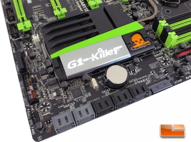
The GIGABYTE G1.Sniper 5 has no shortage of SATA connectivity on board, there is a total of 10 SATA III 6GB/s ports. Six of the SATA III ports are native to the Intel Z87 chipset while the remaining four are from a marvell 88SE9230 SATA III controller which is capable of RAID 1,0, & 10. The Intel Z87 SATA III ports are capable of the same with the addition of RAID 5. To the right of the SATA ports is a SATA power connector, while it may look like it is for the SATA ports, it is actually for the expansion slots. When running more than two graphics cards, you are putting a lot of demand on the motherboard power system, this can alleviate some of that demand by supplying extra power to the PCIe x16 slots. Running up the edge of the Sniper 5 we can see a system fan header, front panel pin out, the second internal SuperSpeed USB 3.0 ports, another system fan header, and finally the first of the two internal USB 2.0 headers.
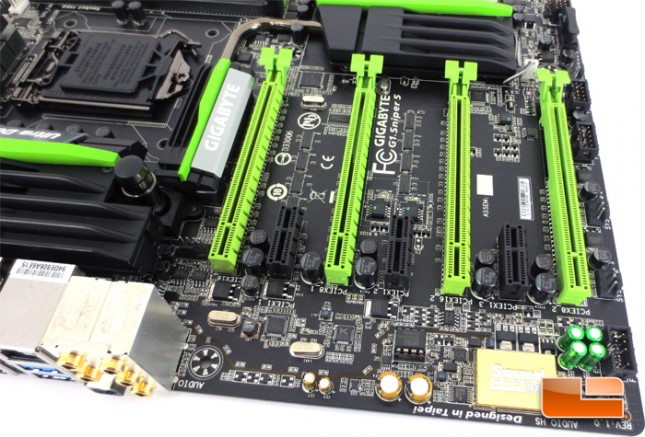
Continuing down the edge of the PCB, we have the second internal USB 2.0 header, a pair of system fan headers, and the front panel audio. There’s no shortage of expansion slots on the GIGABYTE G1.Sniper 5, there is a total of four PCIe X16 slots, PCIEX16_1 and PCIEX16_2 will both run at full x16 bandwidth when utilizing only two graphics cards, these two slots share their bandwidth with the remaining two PCIe x16 slots and all will run at x8 if they are all being used. In addition to the four PCIe x16 slots, the G1.Sniper 5 packs an additional three PCIe x1 slots.
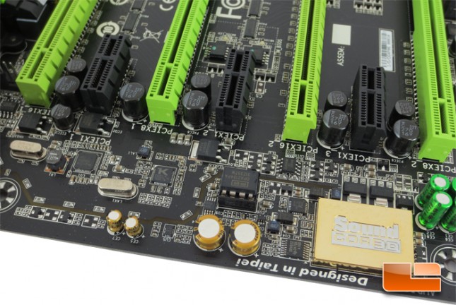
Taking a little bit closer look at the leading edge of the GIGABYTE G1.Sniper 5, we can see the line that separates the onboard audio components from the rest of the PCB. By doing this GIGABYTE can help reduce the electrical interference to the Sound Blaster audio components.
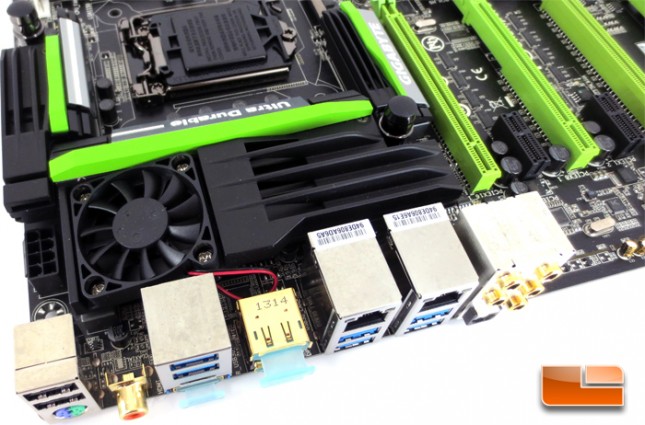
The heatsink on the GIGABYTE G1.Sniper 5 can be run as is, using only the fan, or it can integrated directly into a custom water cooling loop.
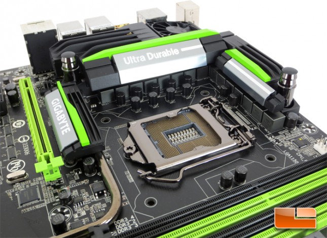
The Intel LGA1150 socket on the GIGABYTE G1.Sniper 5 features 15u gold plated pins within the socket. This will give the socket great conductivity and life span.
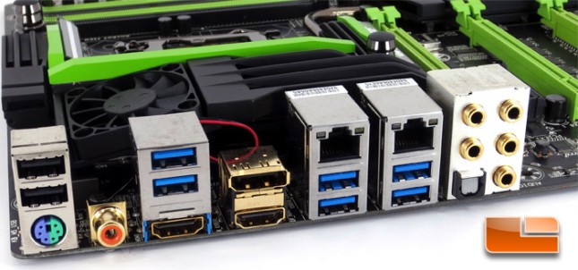
The I/O panel on the GIGABYTE G1.Sniper 5 is pretty typical by today’s standards. The Sniper 5 is equipped with six SuperSpeed USB 3.0 ports, two USB 2.0 ports, a single PS/2 port, dual HDMI, DisplayPort, optical & coaxial SPDIF out, Dual GIGABIT Ethernet, and five 3.5mm audio jacks.