Cooler Master HAF Stacker 935 Case Review
Stacker 925 Mid-Tower Internal Impressions
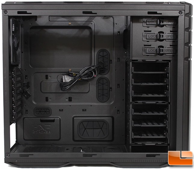
Removing the side panel we can take a look at the interior. The exterior color has continued internally. On the motherboard tray we find four cable management holes that are protected by rubber grommets, and one that is not. In addition there is a rather large CPU support bracket hole in the tray. Cooler Master has included 15 brass standoffs, in addition to the two that are already installed. Lots of room here as it supports up to EATX motherboards.
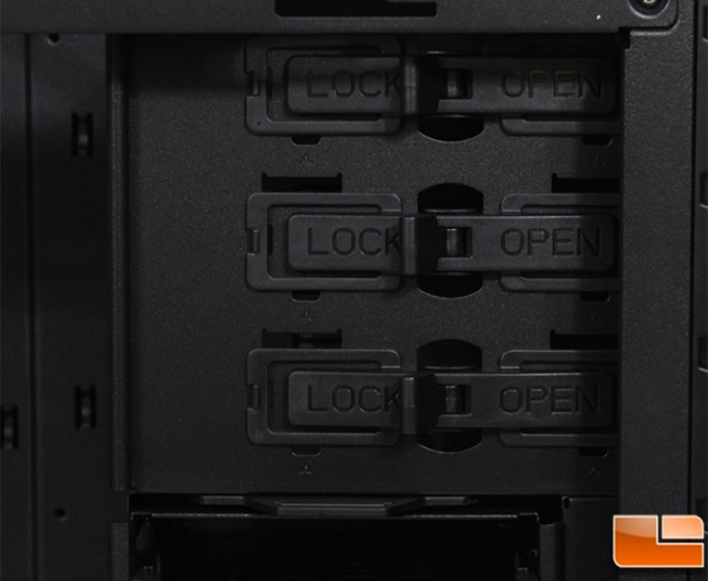
The 5.25″ drive bays are clearly marked how to operate them, flip a switch to either Lock or Open; very easy to use.
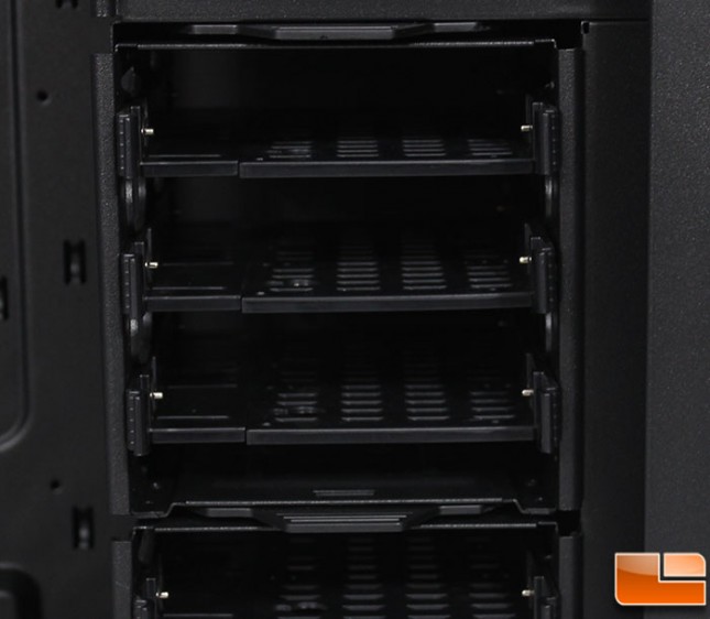
The 3.5″ hard drive bay uses a tray design. There are two of these bays, each one supports six hard drives. The bays can be removed to allow for liquid cooling or extremely long video cards.
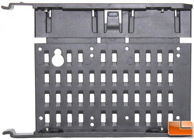
The hard drive trays support both 2.5″ and 3.5″ drives. In addition, they pull apart to allow easy installation of 3.5″ drives.
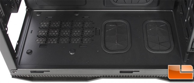
As seen from the exterior, the bottom panel includes the power supply intake and the two large holes. In addition, to support the power supply, there are four standoffs with rubber to reduce vibration.
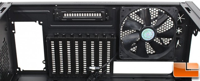
The nine vented expansion port covers are held in place by thumbscrews. Otherwise there is not much to see here.
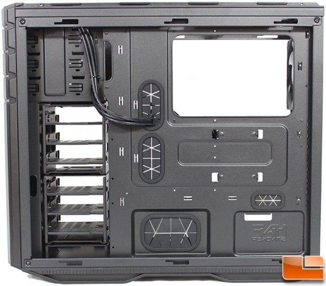
Like most, the back of the motherboard tray is pretty uneventful. From this side, the data and power connections will be done on the hard drives. Below the CPU support bracket is a hidden 2.5 inch hard drive mount. This allows for the six hard drives on the trays, and a seventh behind the motherboard tray. There are a total of eleven cable tie positions, so routing the cables to the appropriate spot shouldn’t be a problem.
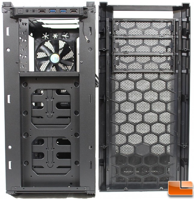
Removing the front bezel is a little tricky as it is held in place very securely by six clips that need to be released from inside the case. Once it is removed we find a fairly normal case. At the top is the front I/O cluster, which has a ground wire to the case. The 5.25″ device bays are ready for installation as there are no guards to be removed. Below those bays are two locations for 120mm case fans, unfortunately none are included so be sure to pick up a couple if cooling will be done with air and not liquid cooling. The bezel itself is actually covered by a filter, and a large honeycomb plastic support frame. The 5.25″ bay covers are easily removed from this side by squeezing a couple of latches together.