ASUS Maximus VIII Extreme Motherboard Review
Legit Reviews Test System
Intel Z170 Test Platform
Here is a quick look at the specific components used in the test system:
| Intel LGA 1151 Z170 Test Platform | ||
| Component | Brand/Model | Live Pricing |
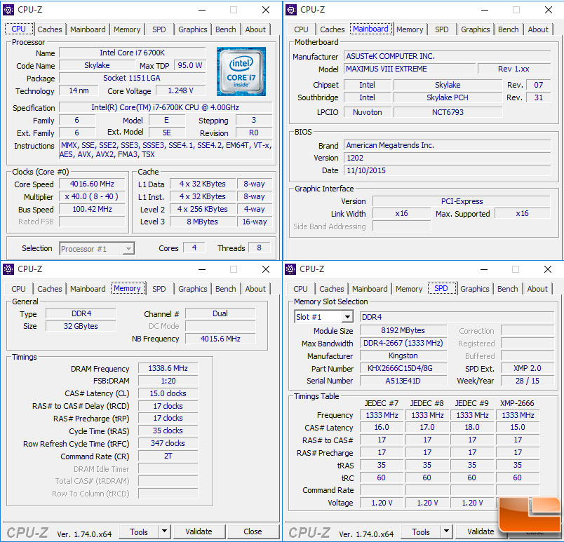
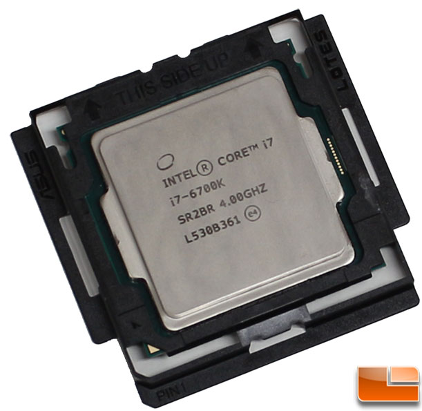
| Processor | Intel i7-6700K | Click Here |
| Memory | Kingston 32GB DDR4 2666MHz | Click Here |
| CPU Cooler | Corsair H105 | Click Here |
| Video Card | eVGA GTX 970 SC | Click Here |
| Hard Drive | Intel SSD Pro 2500 180GB | Click Here |
| Hard Drive 2 | Sandisk Ultra II 480GB SSD | Click Here |
| Power Supply | Corsair CX750M | Click Here |
| USB 3.1 Type C | Kingston DataTraveler microDuo 3C | Click Here |
| Operating System | Windows 10 Pro 64-bit | Click Here |
Testing Process
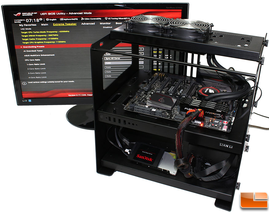
The above listed components will be installed on an open air test bed. Windows 10 will be a fresh install with all the latest patches, drivers and firmware available at the time we begin the testing.
All testing will be done in a temperature controlled room that maintains a 72F (22.2C). A 24-hour burn in is done to allow the thermal paste time to cure before doing any thermal testing.
Where possible, we will use integrated benchmarks, and run them three times averaging the results. In situations where there are no integrated benchmarks, we will use FRAPS to an analyze the performance, doing the same game run three times before averaging the FRAPS results.
Installation Process
The main portion of installing the ASUS Maximus VIII Extreme goes along like every other motherboard. The one major difference comes when you go to install the CPU. Using the ASUS CPU Install tool, the CPU is placed in the tool and then placed onto the socket. You leave the tool on the CPU, rather than removing it. From there, no additional surprises came up.
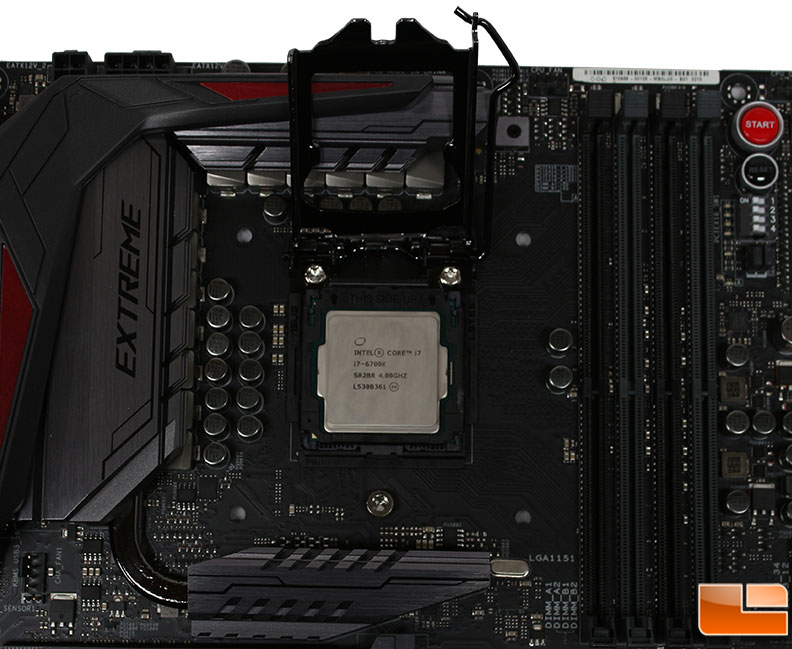
While there are many that will laugh at the notion of a CPU install tool, from a novice standpoint, I can see where it would be helpful. Those pins on the CPU socket are easily bent, and if a little piece of plastic helps keep them from being bent accidentally by a novice, then the tool is a great idea. From my personal viewpoint, outside of doing the motherboard reviews, I don’t see much point to it. Once the CPU is installed on the motherboard, there’s no point to it. For doing reviews though, this does make removing the CPU much easier.
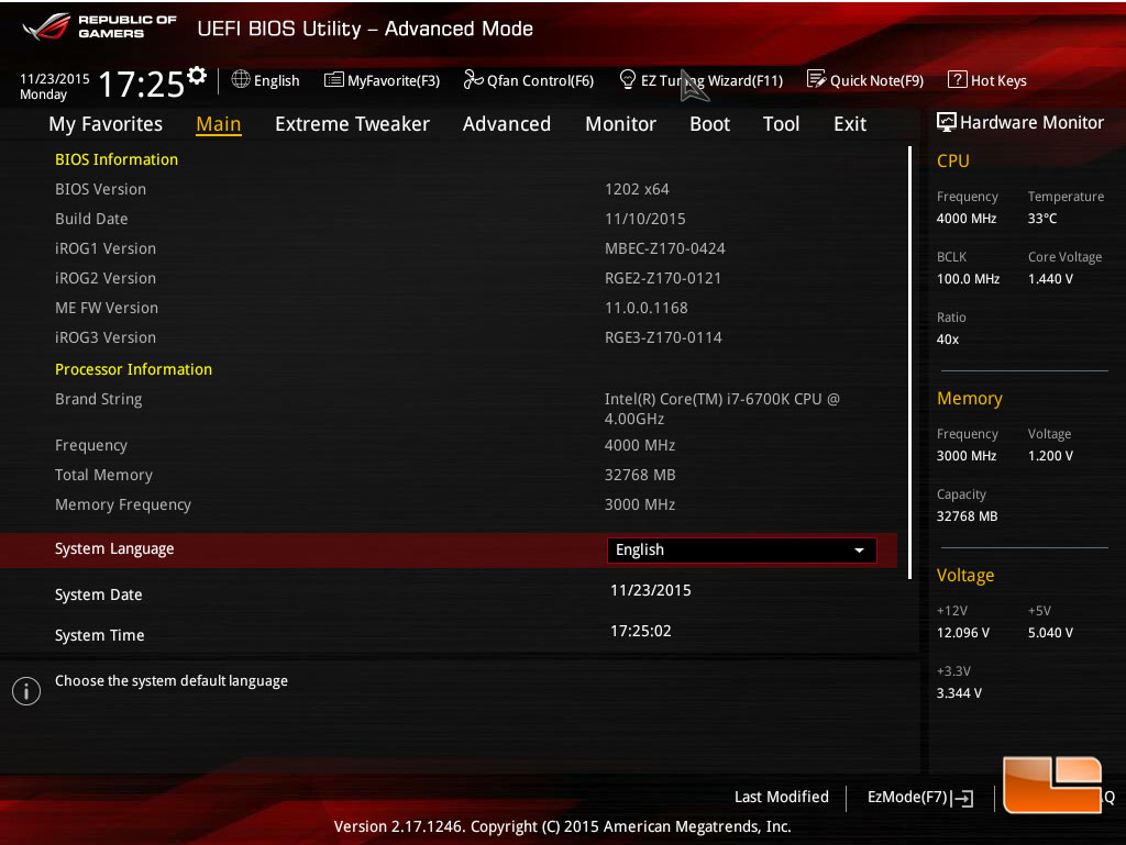
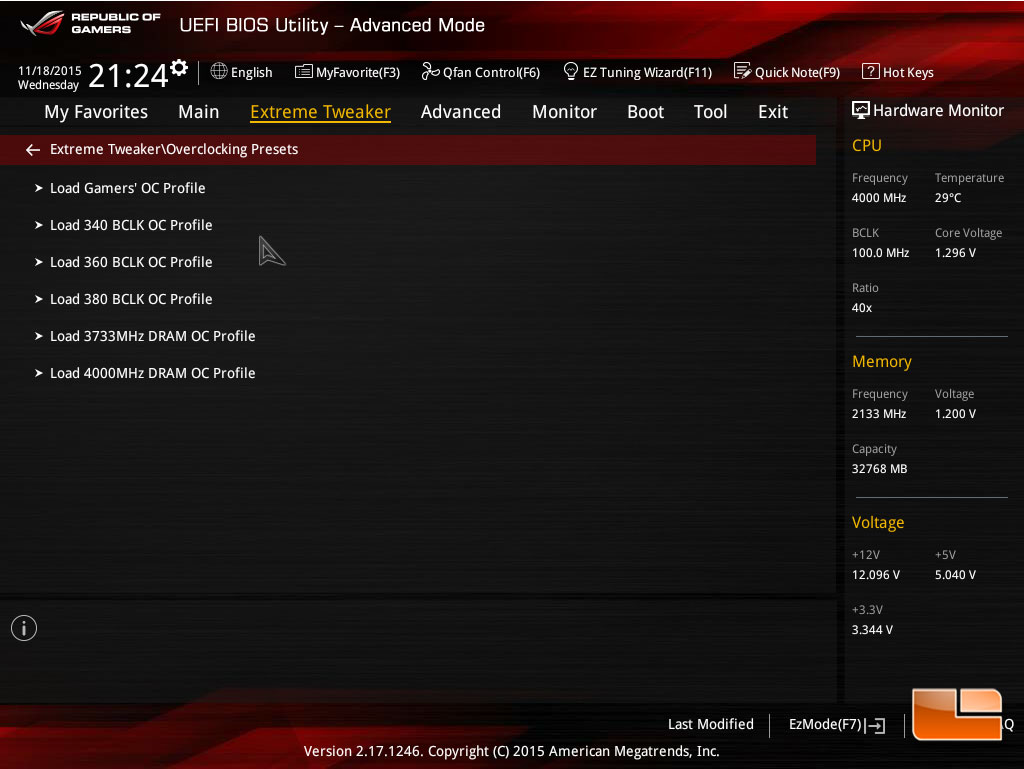
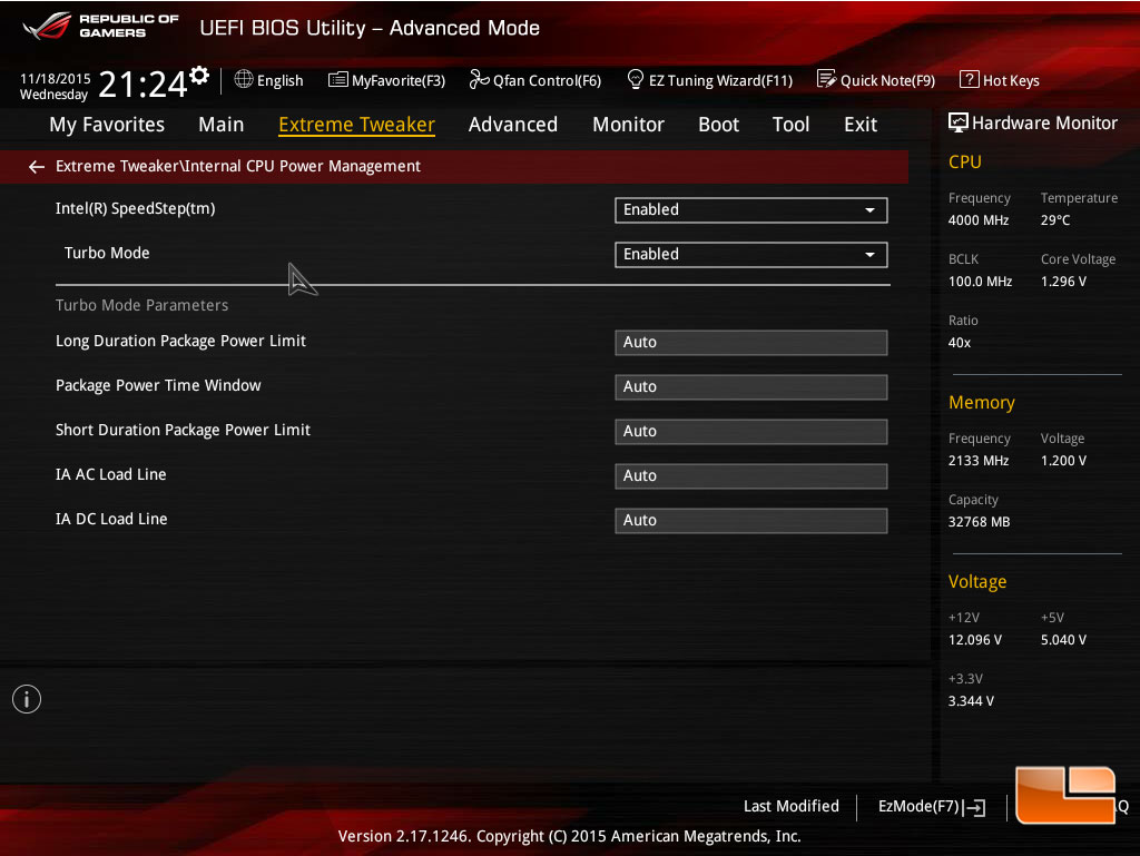
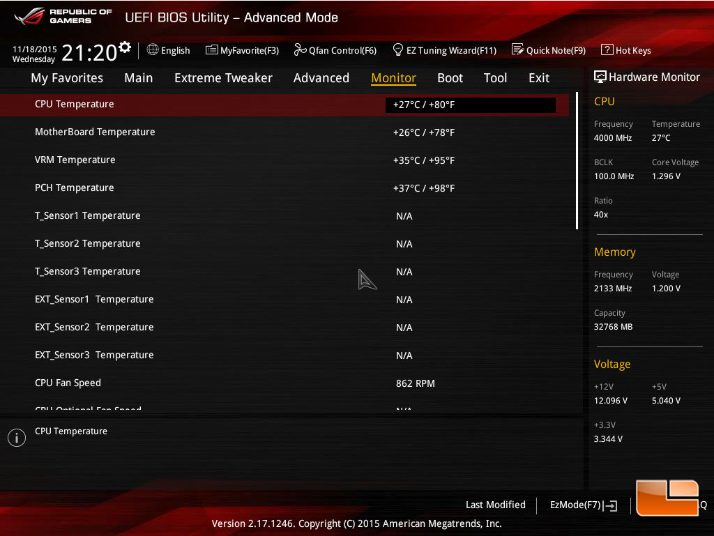
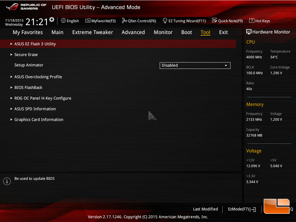
BIOS
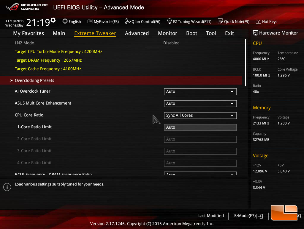
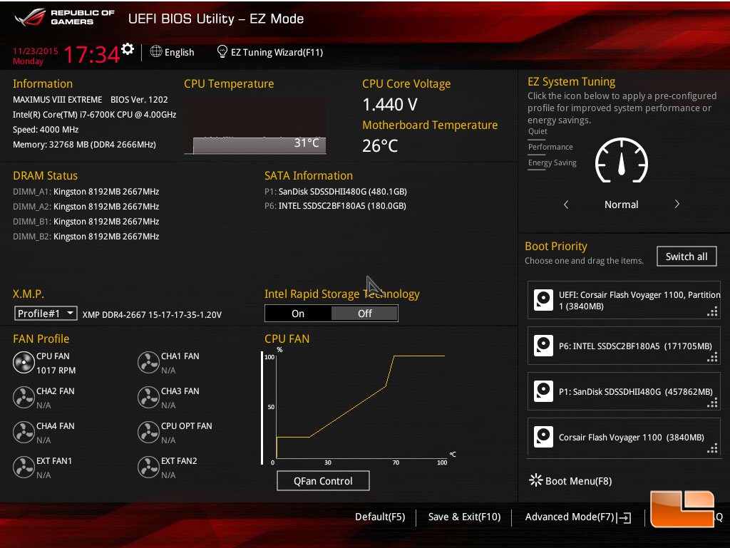
Like most modern motherboards, there are actually two different types of BIOS menu’s, an Advanced and EZ-Mode menu’s. The Advanced menu system is where you can go in and fine tune the system to your particular needs, and is where most of us would spend our time. The EZ-Mode allows making a few changes to the system, such as Performance mode (Normal, Performance, Silent), Boot Priority, Intel RST, XMP status and Fan Control. Otherwise, it is a good place to get a high level overview of the system.
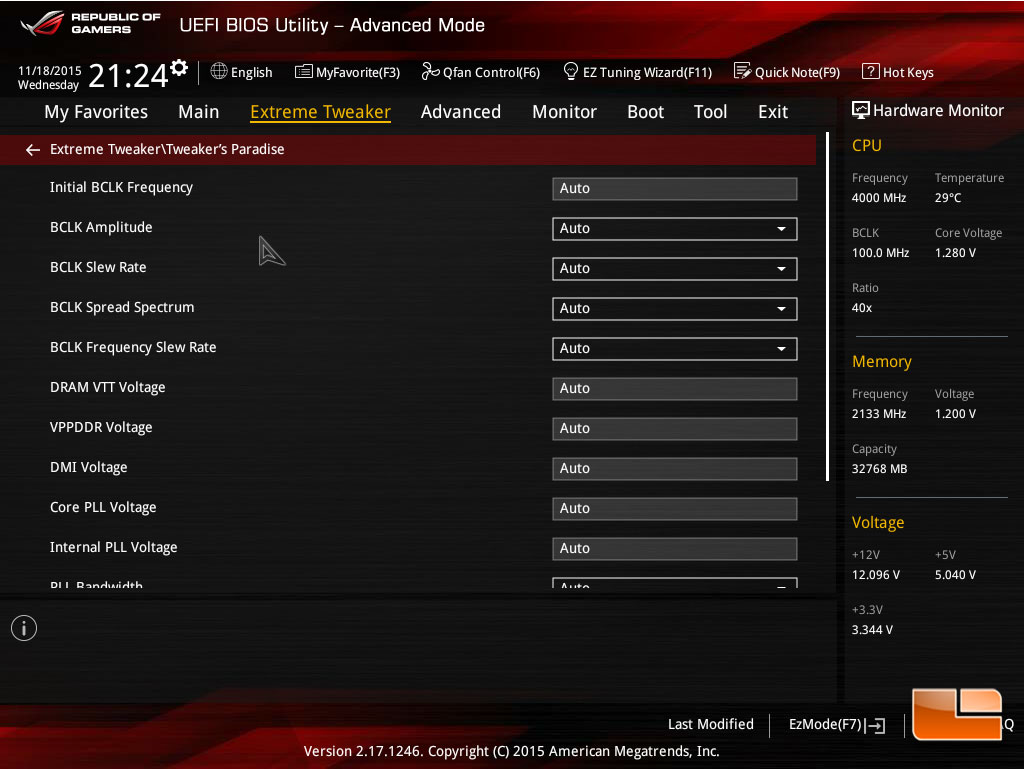
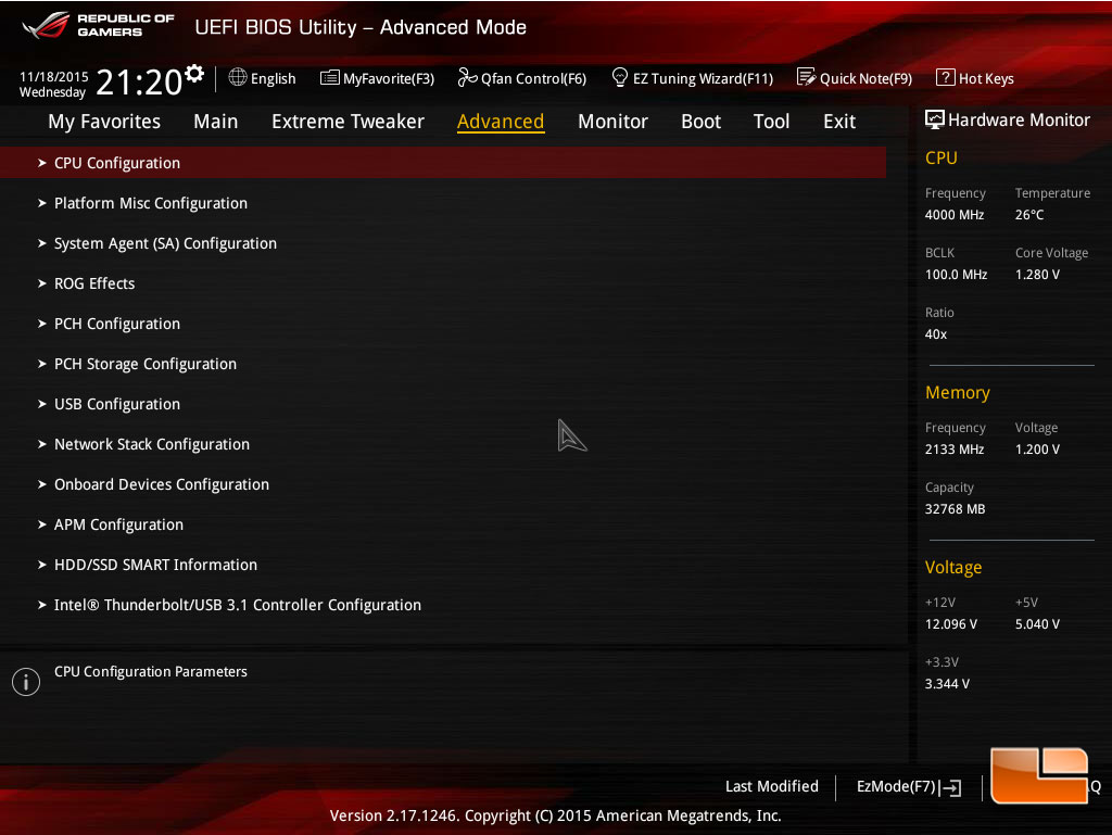
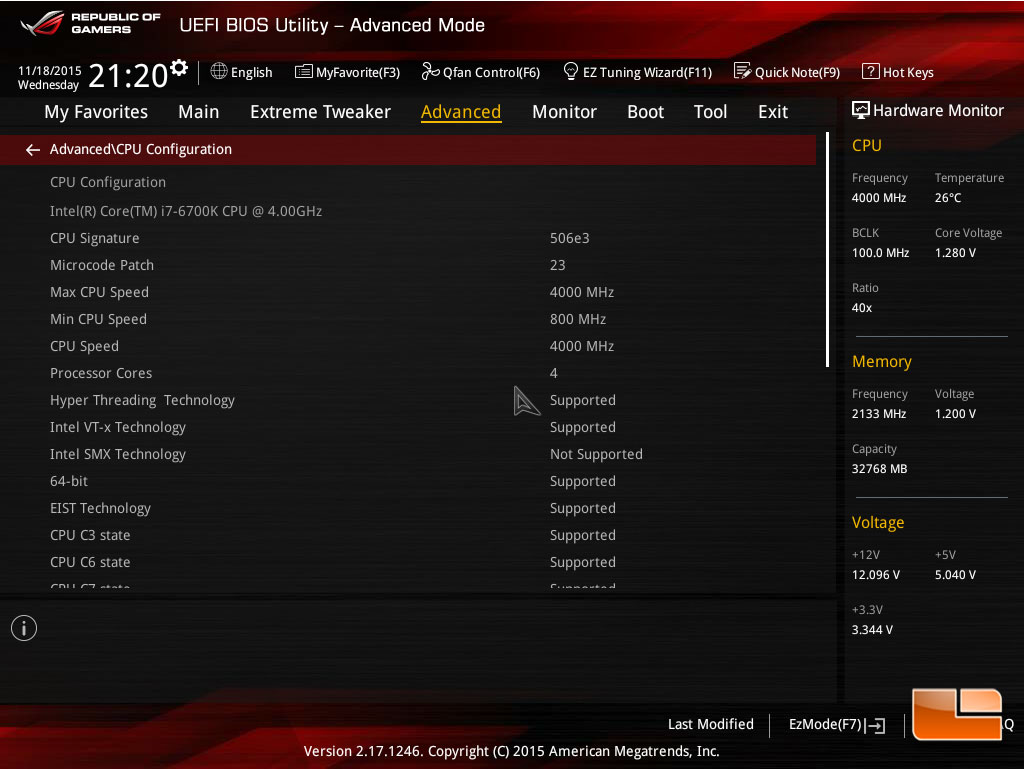
There are many different screens to the Advanced BIOS menu, ASUS does a pretty good job at making things easy to find using many sub-menu’s within their BIOS.

OC Panel II
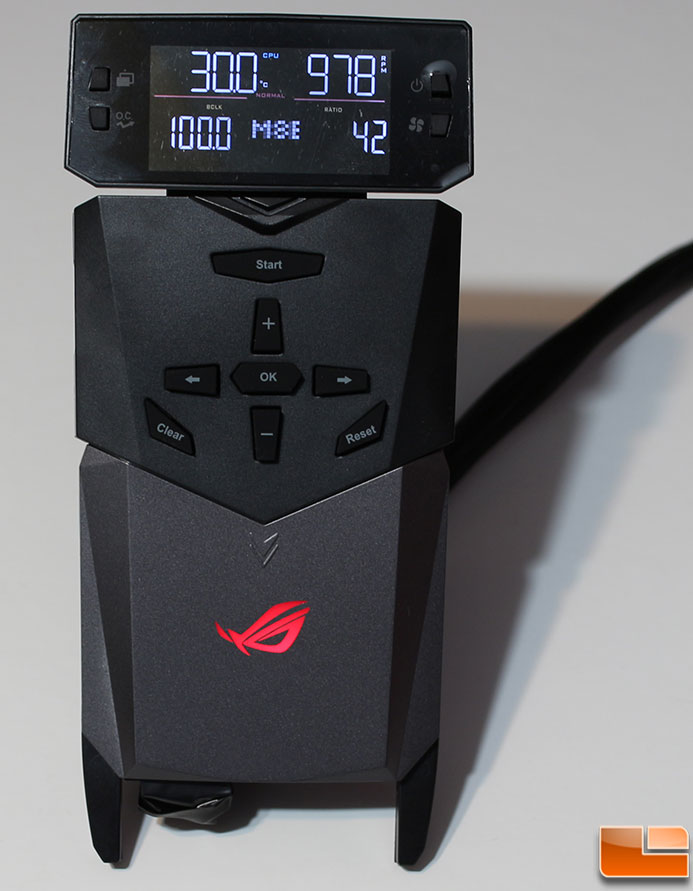
There are two methods of using the ASUS OC Panel II, as an external device or installed in the 5.25″ device bay adapter. In the external mode ASUS has tried to make overclocking and system monitoring easy. Here you have quick access to PWM control, power/reset, overclocking parameters and other ASUS ROG features. Not to mention the additional features hidden beneath the panel which includes thermal sensors, fan headers, ASUS VGA Hotwire connector, and a pair of switches for “Slow mode” and Pause.
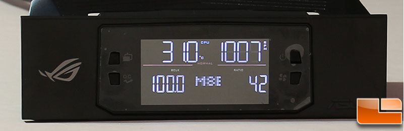
In the second mode, it can be installed into a 5.25″ device bay, and then it provides real-time system monitoring. It provides an easy way to see the CPU temperature, BCLK, Ratio and fan speeds. It also makes it easy to switch between the different performance modes, Turbo, Standard and Silent.
Fan Controller
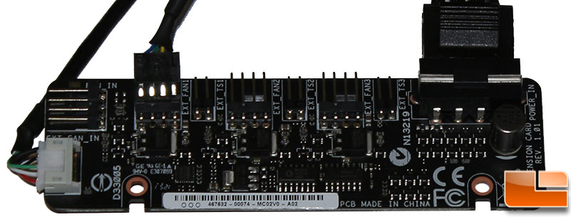
Enabling and using the included fan controller module is extremely easy. There is a five pin cable that connects the module to the FAN_EXT header next to the USB 2.0 headers, connect a four pin Molex for power, up to three fans, three thermal sensors and you’re all set. Now all these fans will be individually controllable. If however, you want them all to report as the same device, you can connect the four-pin PWM fan connector to a fan header on the motherboard instead of the five pin connector, then they will be controlled with whatever profile you select for that specific fan header. In using the fan control module, the biggest issue is where to mount it within your case, there are a couple of holes to put screws through, but it’s up to you to decide on the location and how to mount it.