ASUS Maximus VIII Extreme Motherboard Review
ASUS Maximus VIII Extreme Layout
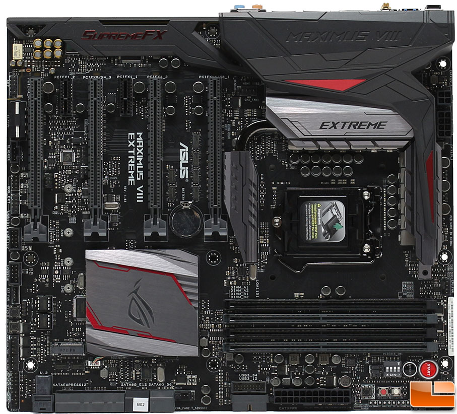
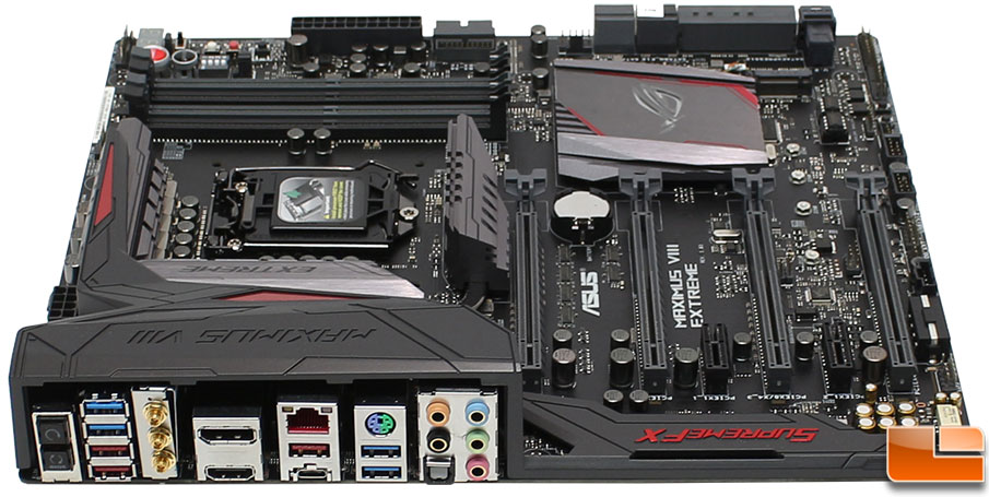
Overall, the ASUS Maximus VIII Extreme has a black and gunmetal grey color scheme, with a few red highlights. ASUS has installed a large cover over the Audio components that extends to become a rear IO port cover, and then changing again into a cover of a large heatsink system that surrounds three sides of the CPU socket working to cool the MOSFETS and VRM. This motherboard is an eATX board, which makes it a little bit larger than standard ATX boards, measuring 12 inches x 10.7 inches; making it just a little more than 1 inch bigger.
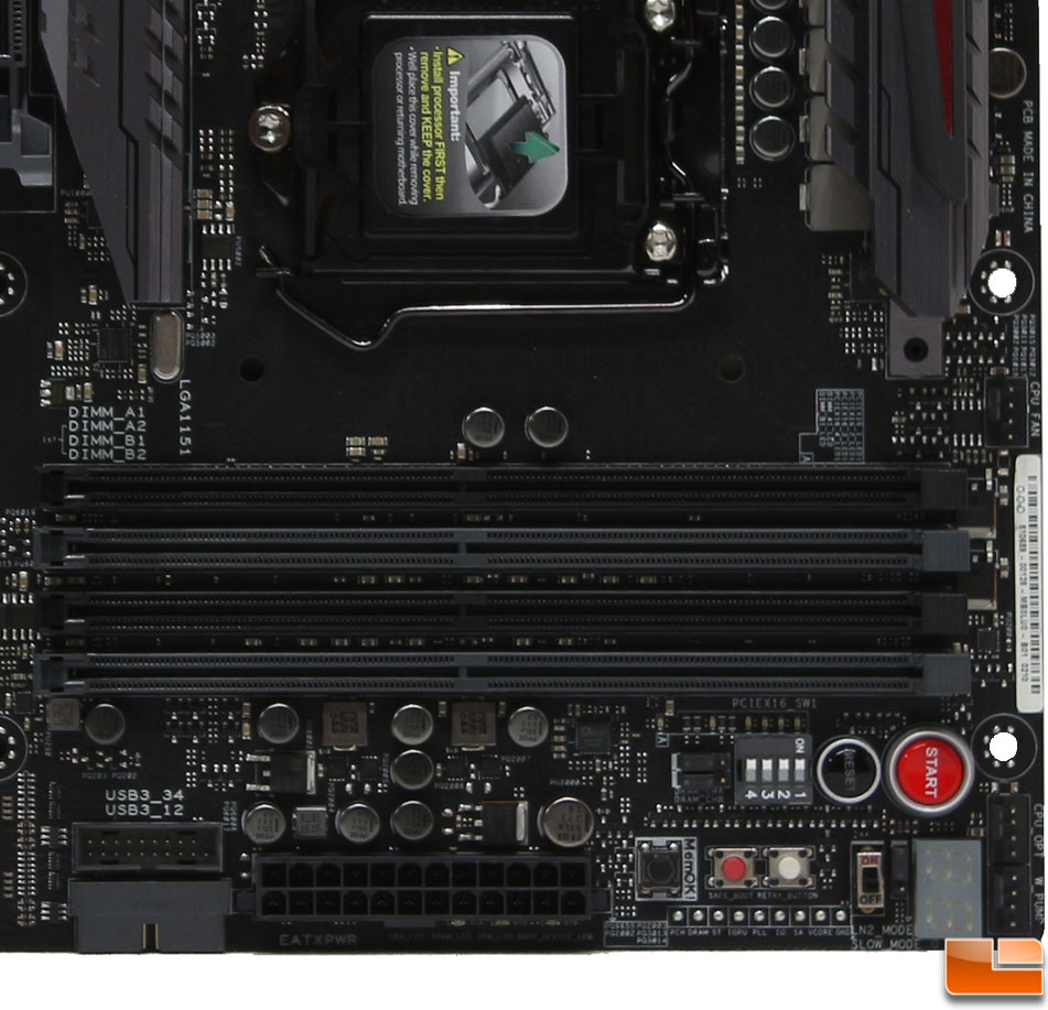
There is a lot to take a look at in this first section of the motherboard. Here we find the four DDR4 slots that is capable of running 64GB of memory at 3866MHz when overclocked. If you are using only two chips, you will want to use the grey slots (A2 and B2) first. Starting along the right edge of the board, we have two fan headers (CPU_FAN and CPU_OPT), and in the corner a W_PUMP connector for a water pump. To the left of the 24-pin ATX power connector is two SuperSpeed USB 3.0 internal headers, one vertical and one horizontal to the motherboard. Below the 24-pin ATX power connector are a couple of tiny LED’s that provide a quick status check on the CPU, Memory, GPU and Boot device. Immediately to the right of the ATX power connector is three buttons, MemOK!, a red “Safe Boot” button, and a white Retry button. MemOK allows you to use non compatible DDR4 memory with the motherboard. Safe Boot boots you into the BIOS when the system is unbootable, for example when an Overclock fails. Retry is for overclockers, to forceably reboot the system while keeping the BIOS settings to try for a successful POST. Below these buttons are voltage check points, allowing you to monitor your systems voltage with a multimeter. Next we find the Slow Mode switch and LN2 mode jumper; both of these are designed for extreme overclockers. Then we get to the debug Q-Code LED. Above all of those, we have a black Reset and red Start buttons. The jumpers are for the PCIe x16 Lane switch, allowing you to disable any of the four PCIe x16 lanes. If you want to disable any of the memory slots, there are two jumpers to do that.
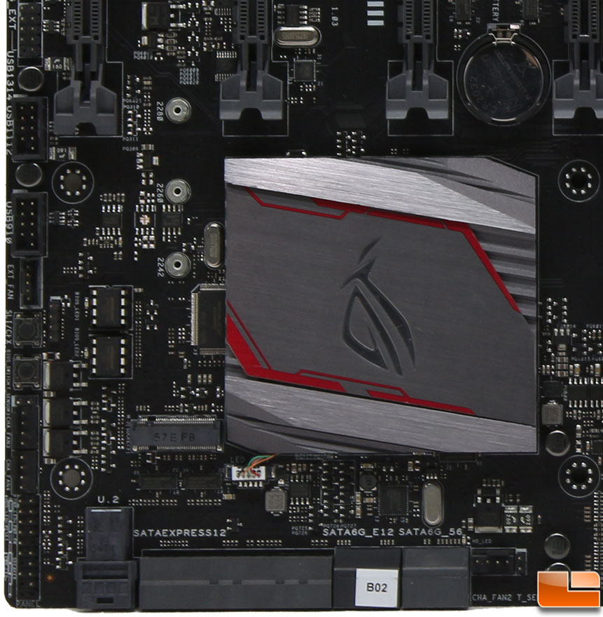
In the corner of the motherboard that has the Intel Z170 chipset, we find that it has a large heatsink on it. This heatsink includes the ASUS ROG logo, which lights up with an RGB LED. We also find a large number of connections in this section. To start, to the right of the SATA connections, is a PWM fan header labeled as CHA_FAN2 and the T_Sensor for an optional thermal sensor. Moving to the left edge of the motherboard, we find the front panel connectors that we will use with the ASUS front panel connector. Next we have two additional fan headers, listed as CHA_FAN3 and CHA_FAN4. Next is another two pin T_Sensor, then two buttons. The first button controls which of the two BIOS chips you are using, while the other indicates which of the PCIe slots are the recommended configuration for SLI/CrossFireX. Then another PWM fan header listed as EXT_FAN for the add-on fan controller, and the USB 2.0 headers.
The ASUS Maximus VIII Extreme has no shortage of storage options. There are a total of eight SATA 6Gb/s connectors, which if you use either of the two SATA Express connectors. Six of the SATA ports are provided by the Intel Z170 chipset, while the other two are provided by the ASMedia ASM1061 controller (the black ports). There is also the latest U.2 connector that operates on a PCIe 3.0 x4 connection to provide the fastest data connection currently possible. One thing to keep in mind, while the motherboard supports M.2, U.2 and SATA Express, the M.2 slot shares bandwidth with the U.2 and SATA Express 1 slot.
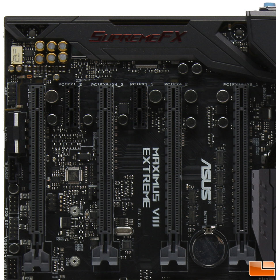
The PCIe slots include four PCIe 3.0 x16 slots, and two PCIe 3.0 x1 slots. Breaking the four PCIe x16 slots down, the first three slots are designed to run at x16 or dual x8 or x8/x4/x4, while the four slots runs at x4. Going up the left edge of the motherboard, we find the header for the OC Panel (this includes a USB 2.0 header), Thunderbolt connector, EZ Plug (which is a four pin Molex power to provide extra power when using multiple graphics cards), and the front panel audio header.
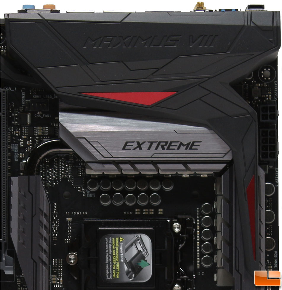
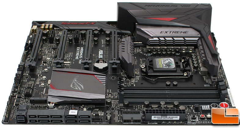
The final area we find a couple connections. First we have the final fan header which is just above the exposed headpipe, and is listed as CHA_FAN1, and another thermal sensor header. The CHA_FAN1 header makes a total of seven PWM fan headers on the motherboard. Along the right edge of the board is both a four-pin and eight-pin ATX power connections. The rear I/O cover is plastic, which also covers part of the large heatsink that is covering the power OptiMOS MOSFETS, dual DIGI+ PWM controllers, and the MicroFine alloy chokes. The Japanese black metallic capacitors still exposed, they look great with their highly polished finish. At first glance, I thought maybe the word EXTREME would be lit up like the ROG logo on the Z170 chipset, however it doesn’t light up. Would’ve looked really cool if it did.
Taking a look at the back panel I/O we find many usual items, and several unusual ones. Starting from the left we have the Clear CMOS and USB BIOS Flashback buttons on motherboards designed to be overclocked, a BIOS reset button is a must have. In the first USB cluster we have two USB 3.0 and two USB 3.1 Type-A connectors. Next comes the integrated 3×3 dual band WiFi solution that supports up to AC at 1300Mbps. Using Intels integrated IGP, you can use the included HDMI 1.4b and DisplayPort connections. Next comes the Intel I219-V Gigabit Ethernet jack, a USB 3.1 Type-A and Type-C (with Thunderbolt 3 support) connectors. A PS/2 Combo port provides support for a keyboard or mouse, along with two more USB 3.0 ports is in this grouping. The final cluster is the audio cluster, which includes five 3.5mm audio jacks and a SPDIF port.
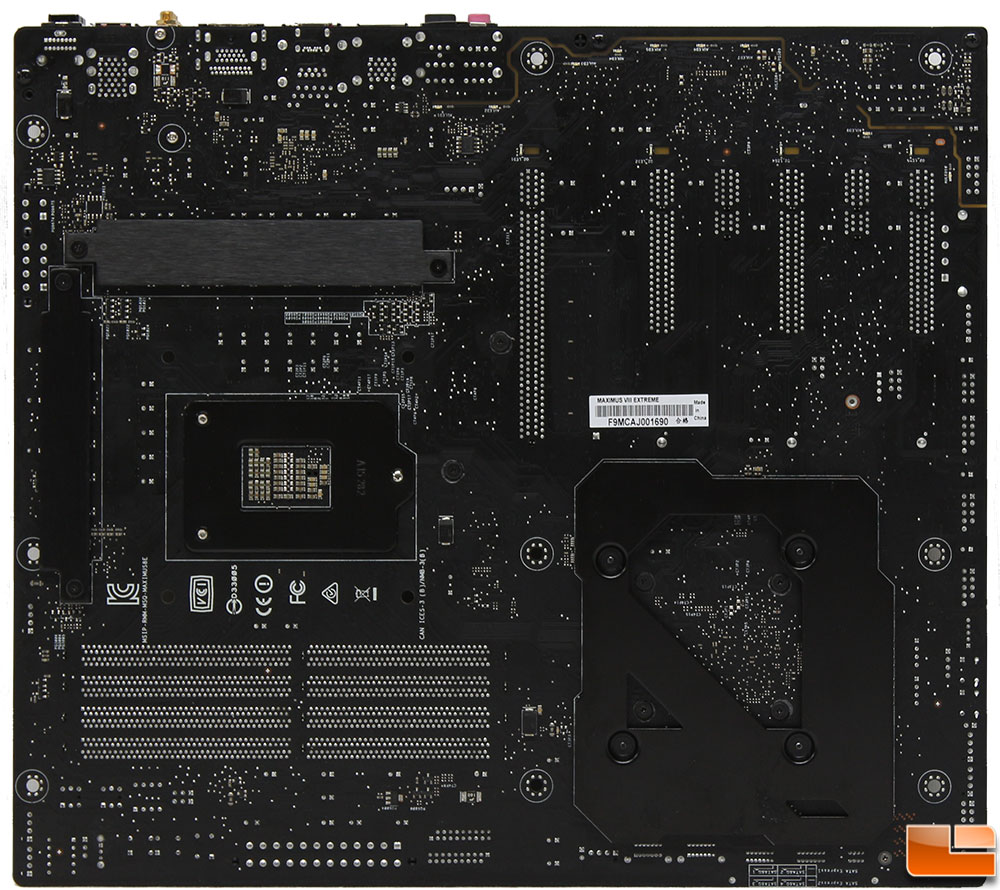
The weight of the ASUS Maximus VIII Extreme was noticed immediately when it was unpacked. On the back of the motherboard ASUS has installed a couple of heatsink support brackets. Of course we have the standard bracket for the CPU socket, but there are also three other support brackets; one for the Z170 chipset, and two for the large heatsinks around the CPU socket.
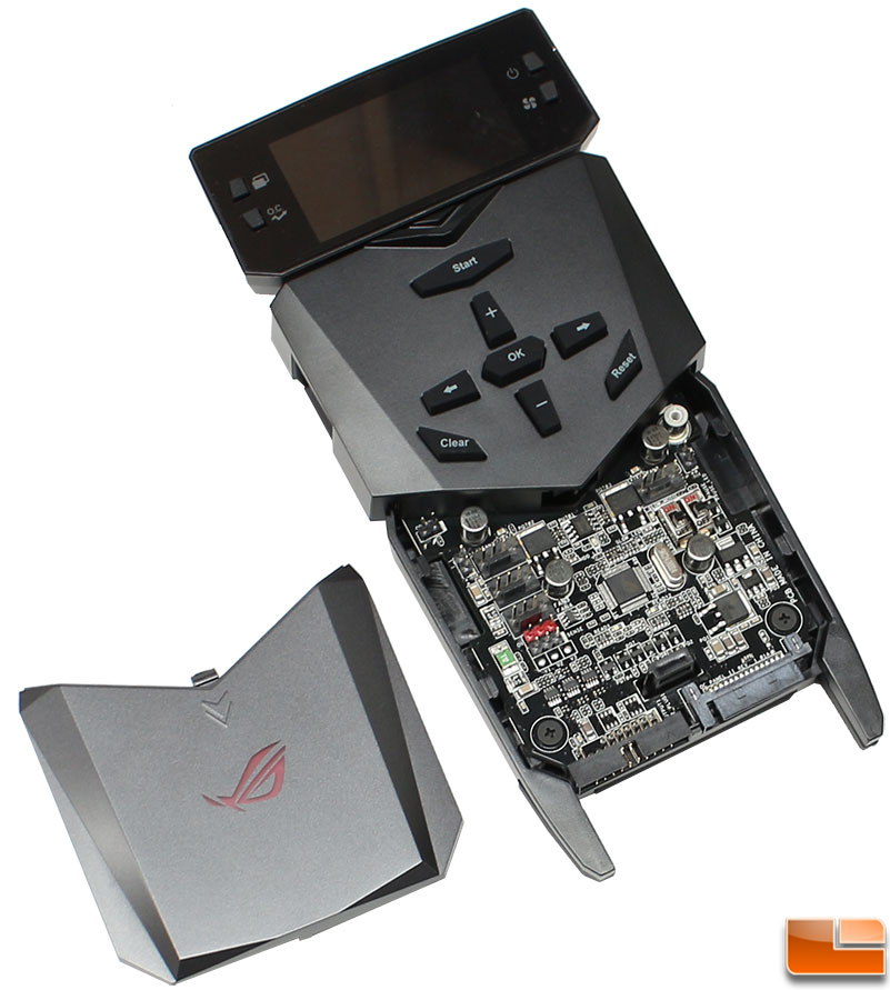
The OC Panel II offers a wide range of features in either of the two modes. In the internal mode, you get access to the display, which is designed to provide real time monitoring of temperature, system clocks and fan speeds, plus makes it easy to change performance mode. In the external mode, you get access to the same information, however you have access to the buttons on the front of the OC Panel II, and the connections beneath the hidden door. The OC Panel II comes with a fairly short cable, measuring 2ft 8in, and you are also supposed to connect a SATA power connector, while this won’t pose any issues in the internal mode, I wonder how well that will work as an external device unless the system is in an open air test bed.